My Journey into Metal Fabrication is something that I witnessed myself doing in my dreams. I bought a welder, a 7-inch cylinder of C25, a welding hood in 2019, and an angle grinder. It all just sat. But, I knew I wanted to weld. And, I’ve wanted to buy or build a plasma CNC machine for over 20 years. Something was pushing me but I can’t explain what that push was.
Woodworking was ok but it wasn’t resonating with my energy. I witnessed many of my friends making cool stuff out of metal like: Chad from Man Crafting, Bernie from Works By Solo, Chris of Make Everything, and Derek From Malden. When I visited Chad and Bernie in Atlanta I got to operate Chad’s laser and made an engraved tumbler for Johnny and one for me. That really pumped me up.
They fueled my dream and I think gave me purpose. I don’t know what I’m going to make. But, just the thought of being able to whip a welder out and start gluing metal together gives me goosebumps.
Being an ok woodworker from birth I do see a future in fusing the arts of metal fabrication and woodworking. Afterall, most of the tools I’ve purchased up until 2024 have been woodworking related.
Fun Fact
Woodworking clamps, combination squares, belt sanders, and combination belt and disc sanders aid in metal fabrication.
Welcome to my Metal Fabrication Timeline
Articulating my thought process throughout this journey is challenging. What I can say is that I have visions of what my workshop including what tools are where and how it’s organized.
November 2023
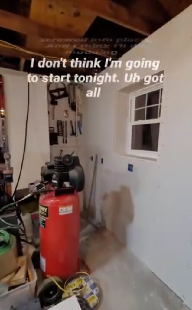
My garage is my workshop but it is not functional with chaos and clutter. It will become my fabricating workshop. To facilitate this transition I need to construct a storage shed to relocate all materials and supplies. You can learn more about this in my DIY Build a Shed series.
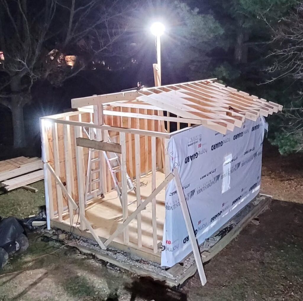
Getting the roof done so I can move everything into the shed.

April 2024
Once the roof was on I began moving stuff into the shed to free up my workshop.
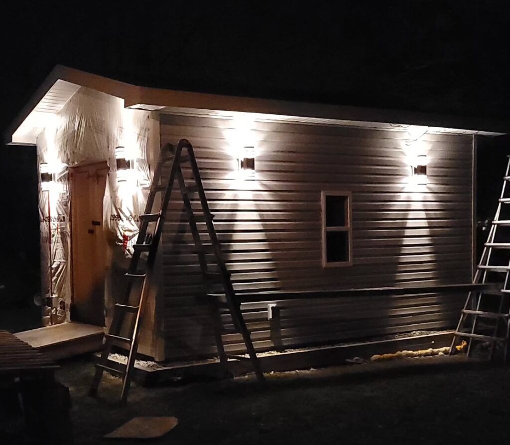
May 2024
My brother-in-law drives past every day after work and stopped to check the status.

July 2024
July 2024 marked the day when things got real. I knew if I bought this that it would just be a matter of time before I built my Plasma CNC machine. My first cut on my plasma CNC was made over a year later
September 2024
My garage would become my workshop. I needed to set the tone. Black is symbolic of metal fabrication.
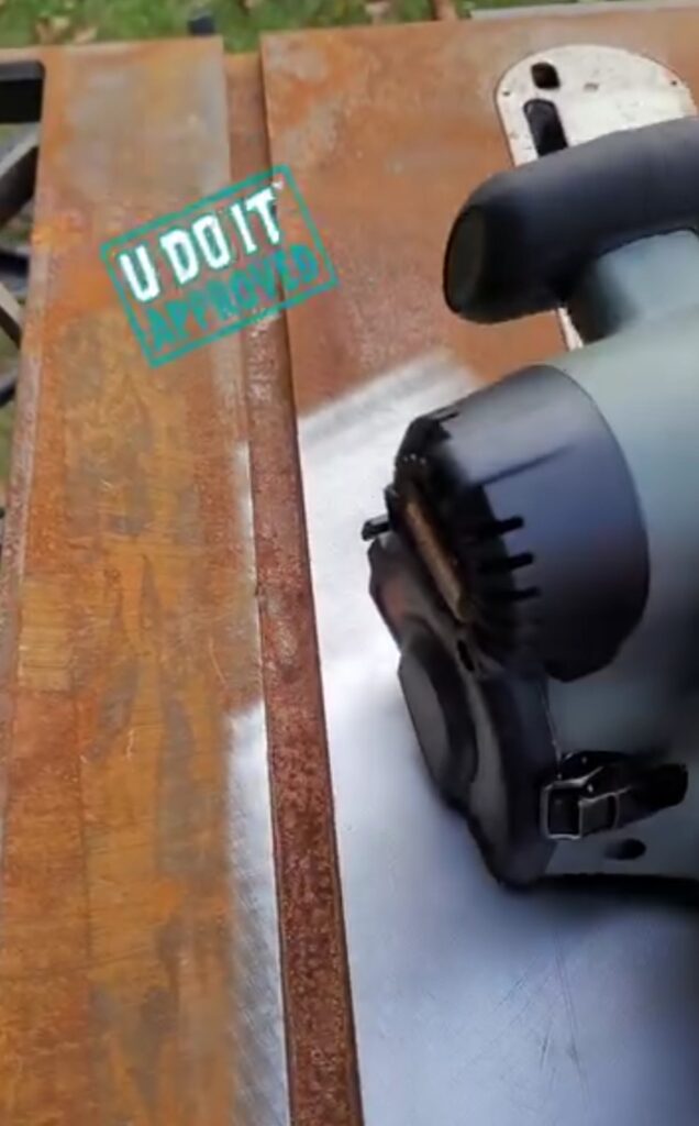
Picked up a table saw just for the top to become a fabrication table. Removed the rust with the Restorer. I have yet to use this table saw top as a fabrication table.
October 2024
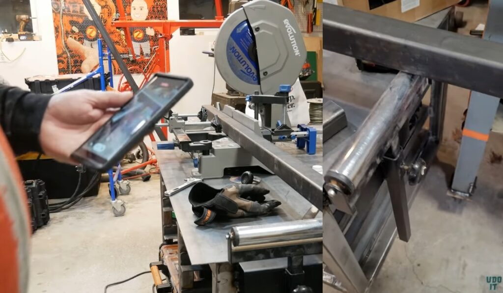
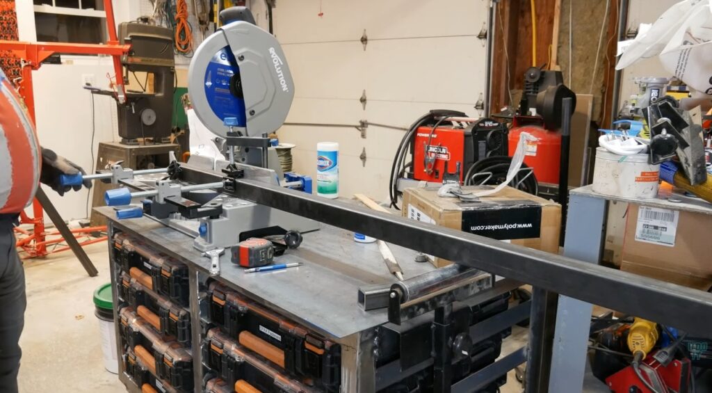
Another tool for accurate cuts was the Evolution Miter Saw that cold cuts steel.
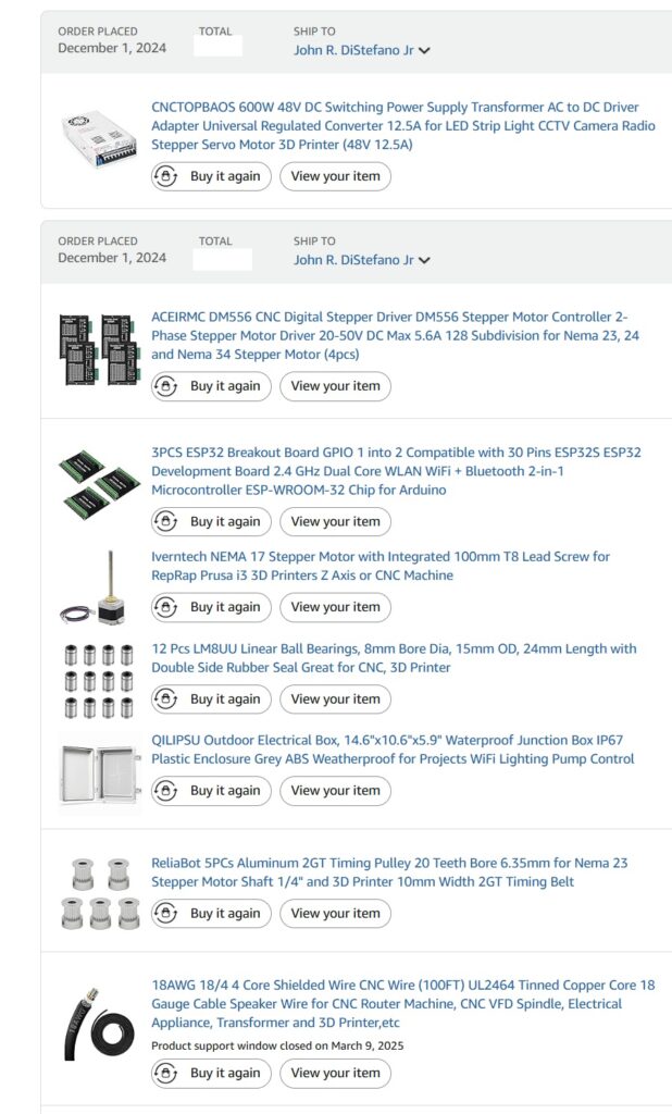
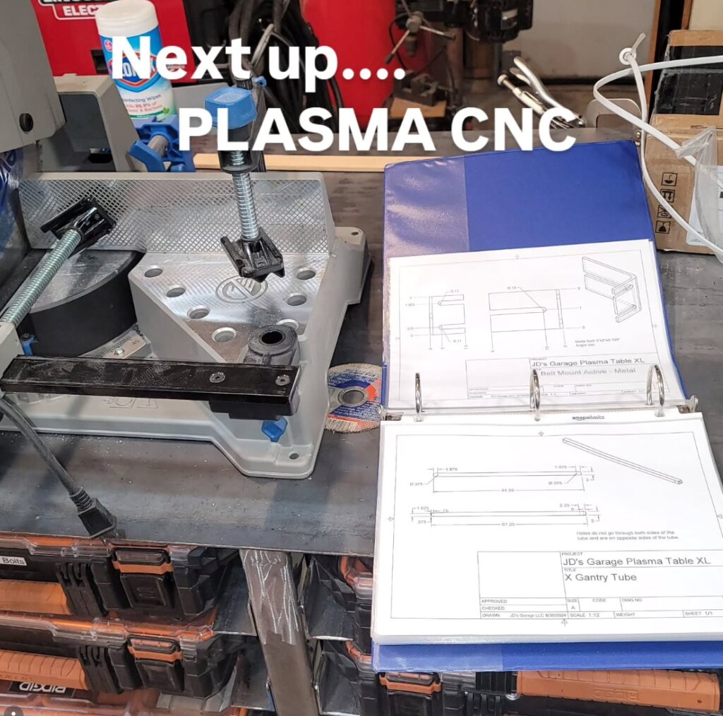
December 2024
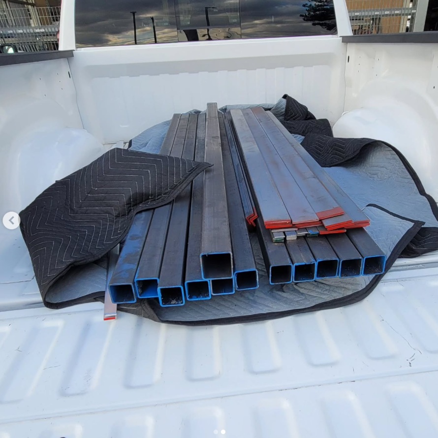
Purchased the steel I need for the Plasma CNC from Fazzio’s. I’m committed to this build now. I’m using JD’s Garage XL Plasma CNC plans for a 4′ by 4′ cutting area. Later, I resize it using their calculator to a 52 inch by 96 inch cutting area.
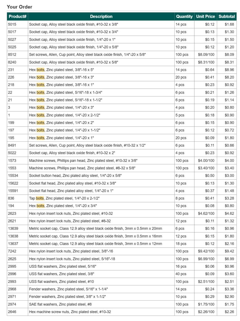
Bolt Depot is a wonderful place. I was able to order the bulk of fasteners as specified in the plans. I added a few extra for most of the pieces.
Knowing that I’ll need proper measurements I ordered some machinists essentials for my workshop, such as precision 123 blocks, steel squares, and Dykem layout fluid. This is me stating to the universe that I am a fabricator.
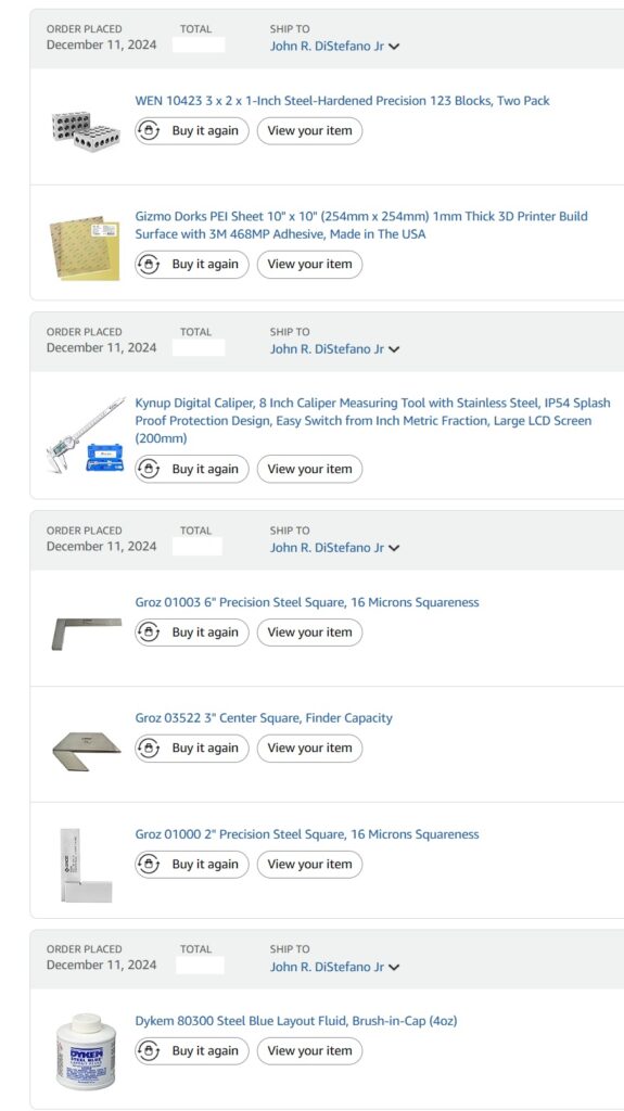
This is a partial glimpse into the components required for the build. It includes mechanical and electronics parts. The main brain is an ESP32 that controls the stepper drivers which drives the NEMA23 stepper motors. The Z-Axis stepper is a NEMA 17 and either I made a mistake or the parts list was incorrect. This one ordered was the incorrect size. But, it recently became invaluable.
January 2025
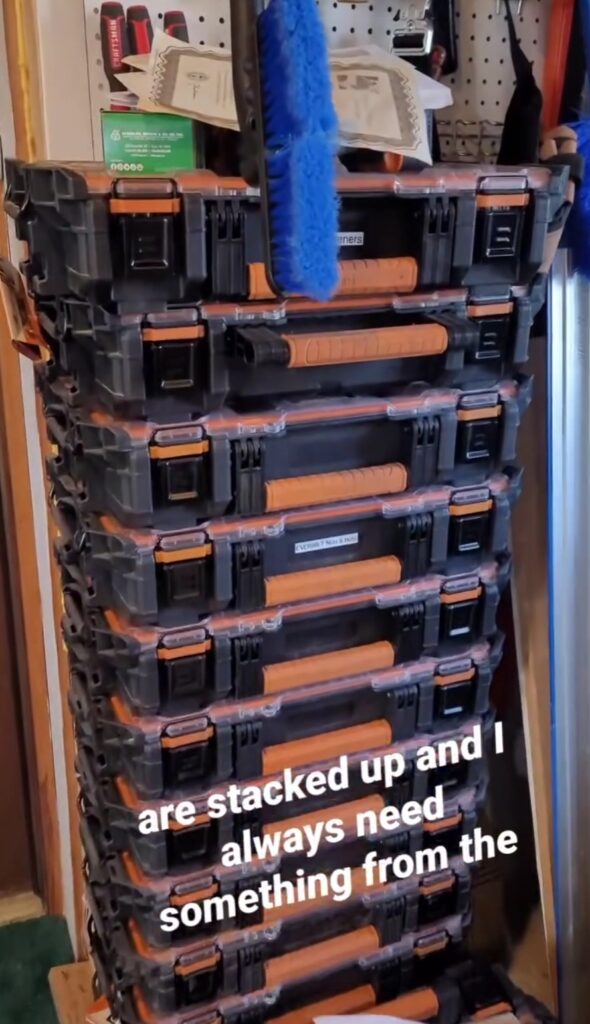
Fasteners are important for any workshop and so is their organization for the workflow efficiency. These RIDGID small parts organizers are great and it’s awesome that they stack nicely. I almost always need a faster from one in the middle or the bottom. That means there’s a lot of jockeying these around.
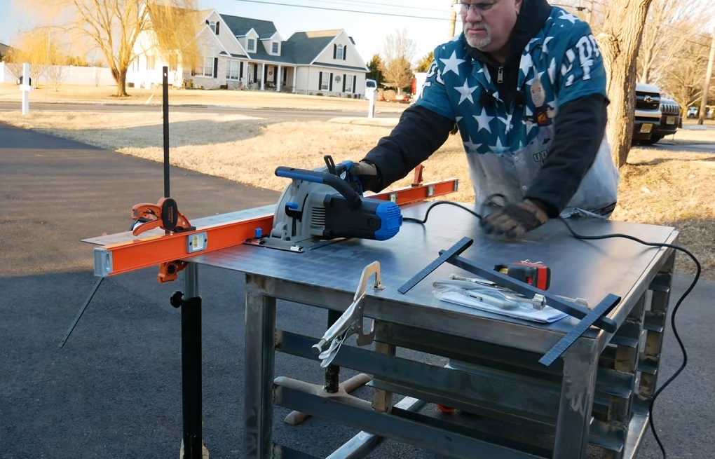
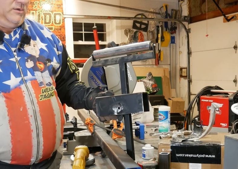
I need a miter saw station that also doubles as a fabrication table and a small parts organizer.

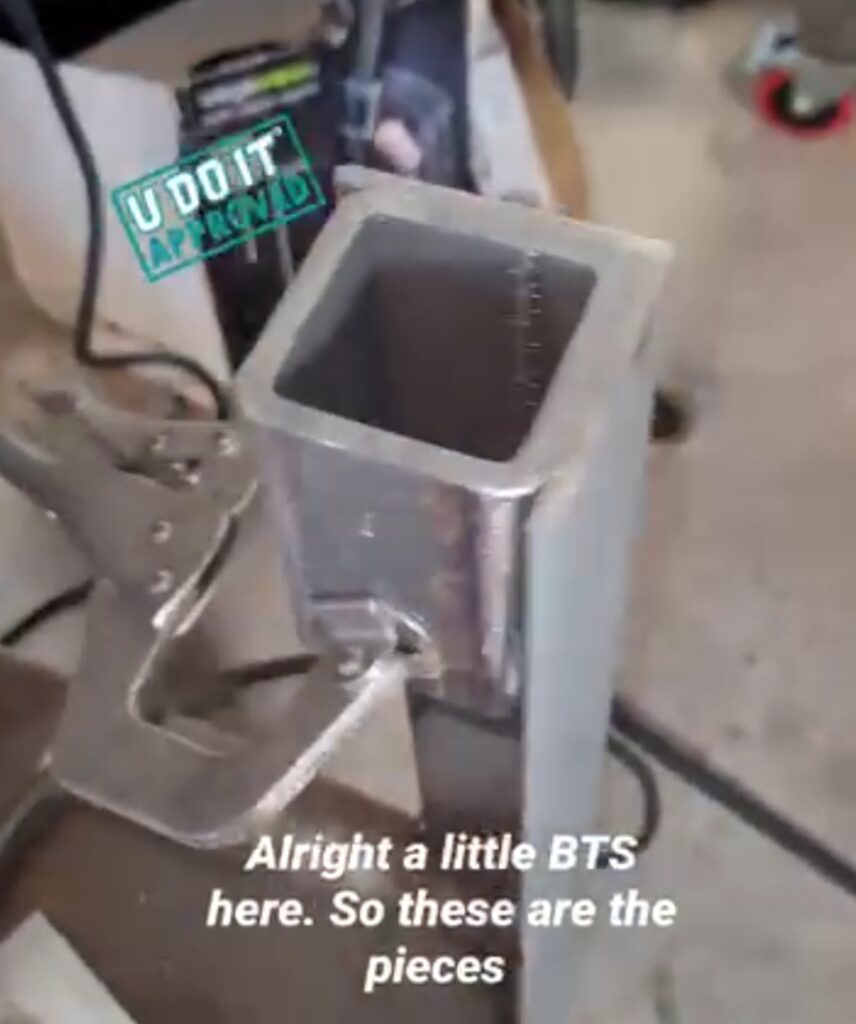
And, I would like this table to be as square and true as I can possibly make it. One way is to ensure repeatability for my cuts by using this stop block for my miter saw that I welded together out of scrap steel.
Grinding off the mill scale using my Eastwood SCT (Surface Conditioning Tool).

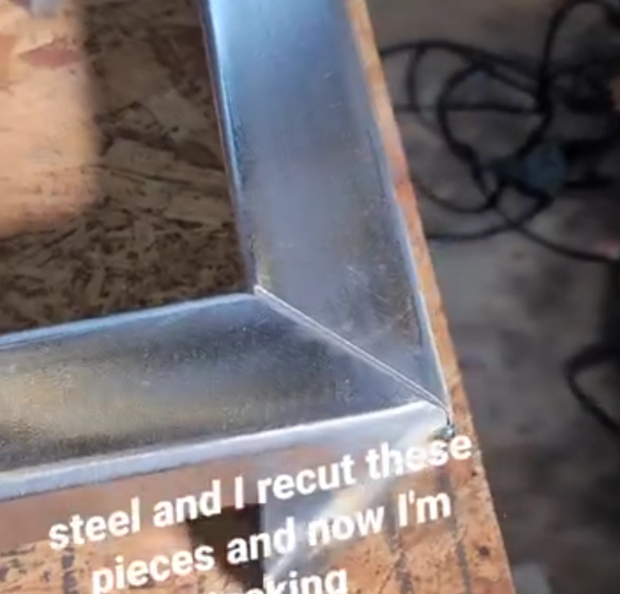
This is the frame for the miter saw station. A perfect miter created by the Evolution miter saw. I grinded the edges down at 45 degrees for better penetration. Notice my tack weld in the middle of the edge? Since this time, which is over a year, I have learned that it is better to tack on the corners where it is easier to grind off.
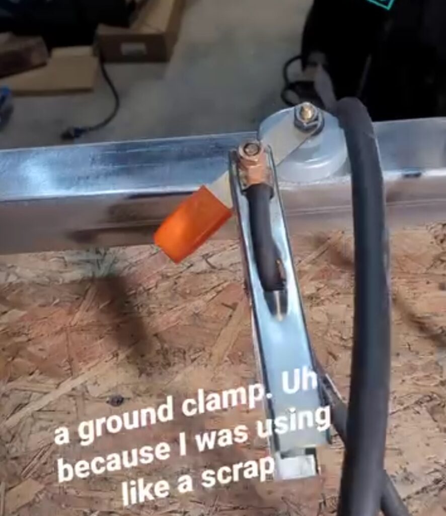
And this magnetic ground clamp is perfect for situation since I do not have a metal fabrication table. That is why I am building this table.
Grinding down the weld at the miter joint.

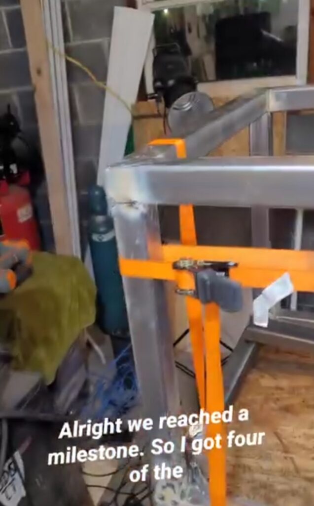
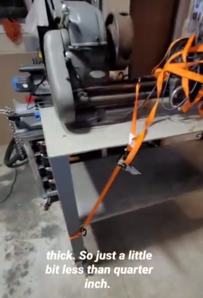
Fabrication sometimes involves using ratchet straps to bring things together. Some cool YouTuber’s out there providing tips stating that we all start at zero. Use what you have and improvise. Notice in this photo that you can see concrete block. As I’m doing this I’m plotting out the next thing I need to build in order to make this workshop functional and safe.
February 2025
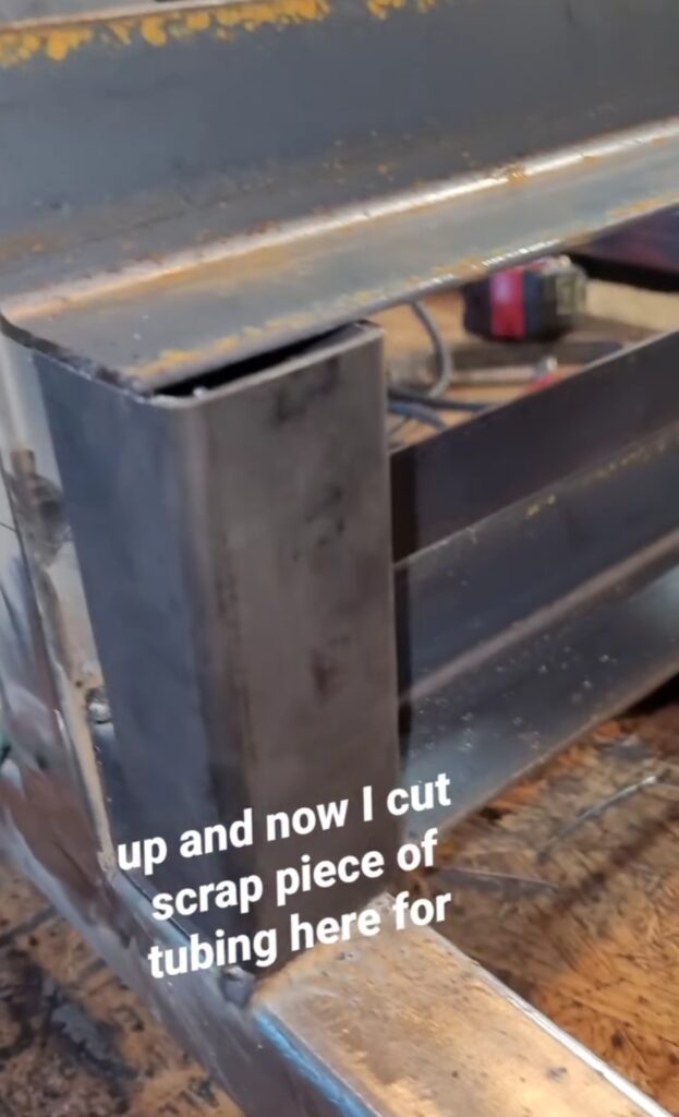
February was a busy month. Welding in angle iron for the small parts organizers using a spacer to ensure repeatability. My math was off which resulted in a clearance problem at the top row. A critical lesson was learned as my spacers were not cut to the correct size. I did not take into account the thickness of the angle iron.
This will be instrumental in the fabrication of my plasma CNC.
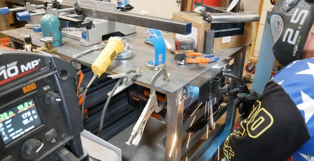
I’m learning that fabrication involves becoming creative with ways to hold pieces together to tack them into place. Here I’m welding the cross members.

Welding in the cross members using flux cored process.

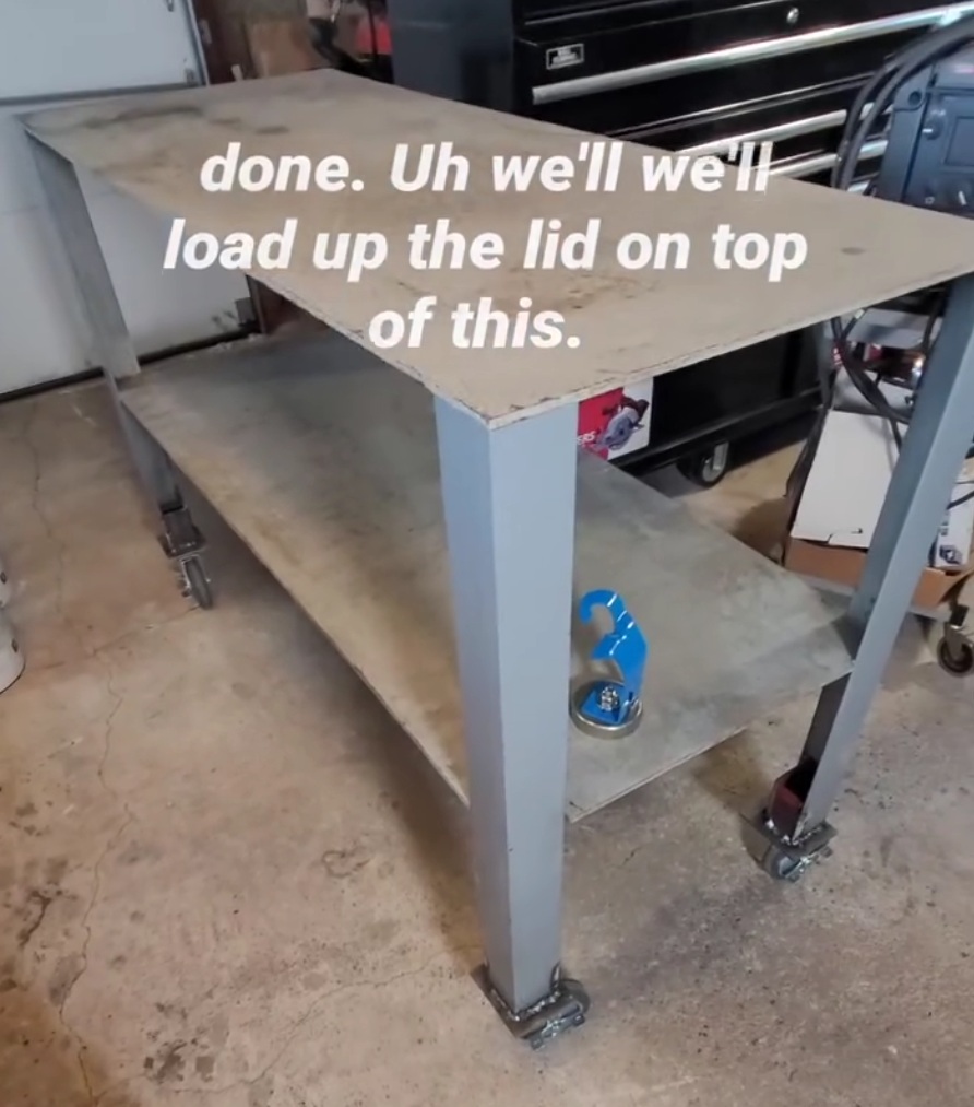
Look of the cart with cross members welded in place to support the heavy weight of the Evolution miter saw and any workpieces that I work on the table top.
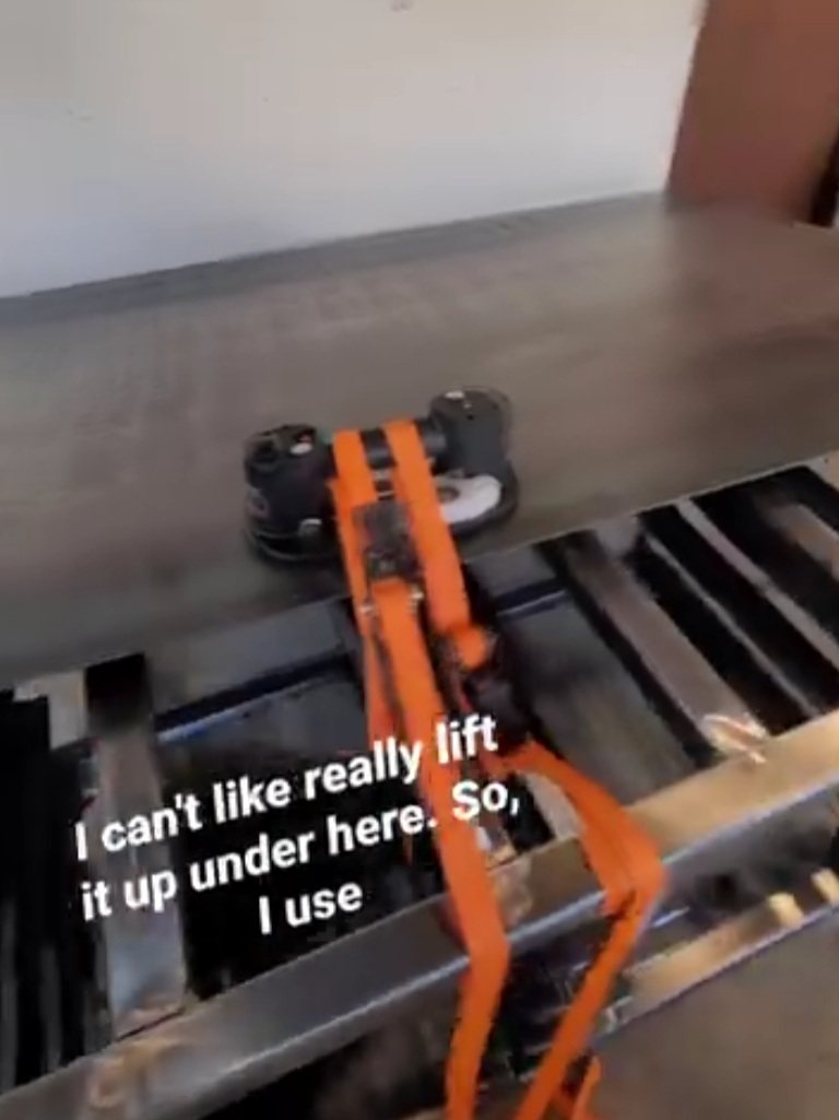
Positioning a 4×8 sheet of 1/8-inch thick steel is challenging by yourself. I used my Grabo pneumatic gripper to help me pull it up on top of the table. I’ll eventually purchase permanent magnetic lifters to do the same.
Moving this to the outdoors for more room to cut it down to size.
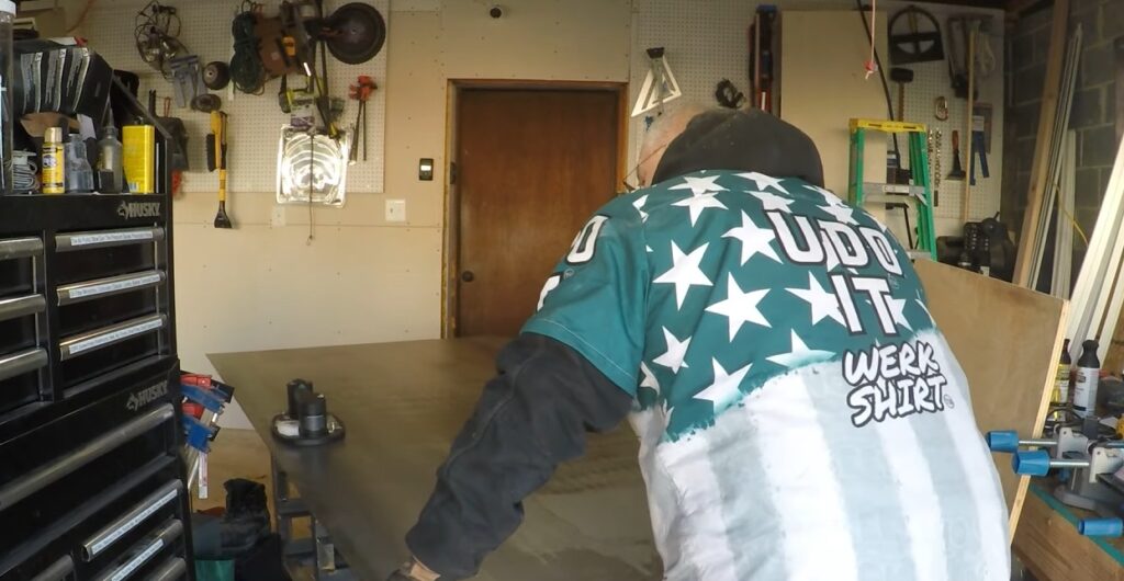
This is the Evolution 8 1/4 inch cold cut circular saw that I’m using to cut the table top down. It literally cuts through this like butter. The edge is a level clamped down with quick clamps. And the sheet extension is being supported by stationary feed rollers. My first cuts on the plasma CNC table are with these off-cuts.
Cuts steel like butter!

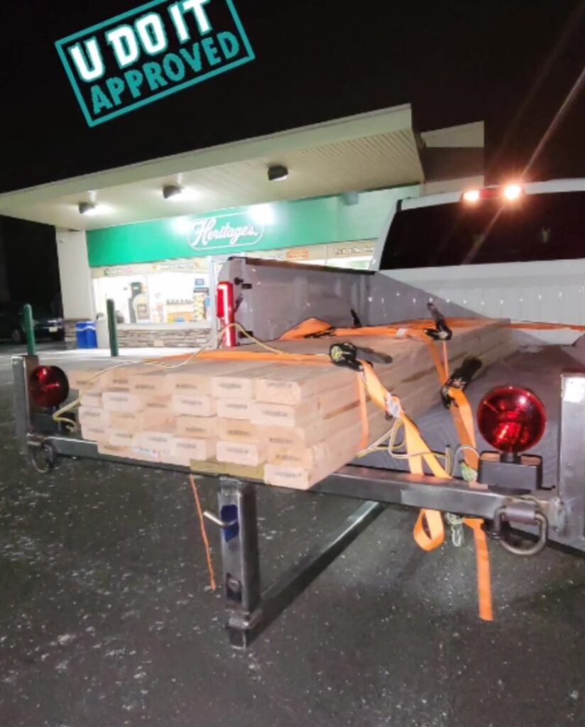
Fabricating a Truck Bed Extender
I learned about Dykem layout fluid and using calipers to scratch the surface for a better mark. Notice the double line, which is the result of using calipers from both rounded edges.

Welding the vertical support to the extender bar.

It fits perfectly.
First test of the bed extender with a Home Depot for lumber to complete the workshop.
Finishing Workshop
During this time I’m also finishing the garage and sealing every hole not just for insulation but for draft blocking using Rockwool and fire blocking foam.
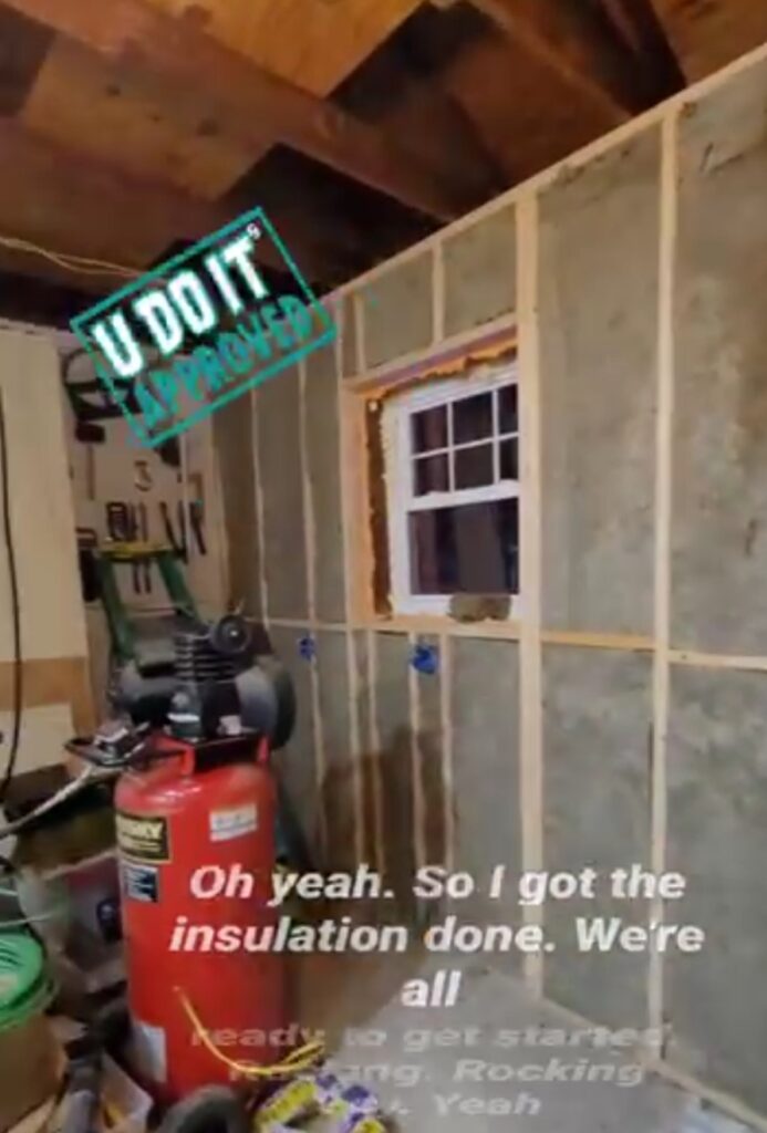
Five sheets of drywall were needed for this wall.
The ceiling is getting some protection, also. This is 5 1/2 inch thick Rockwall for 24-inch on center ceiling joists.
![]()
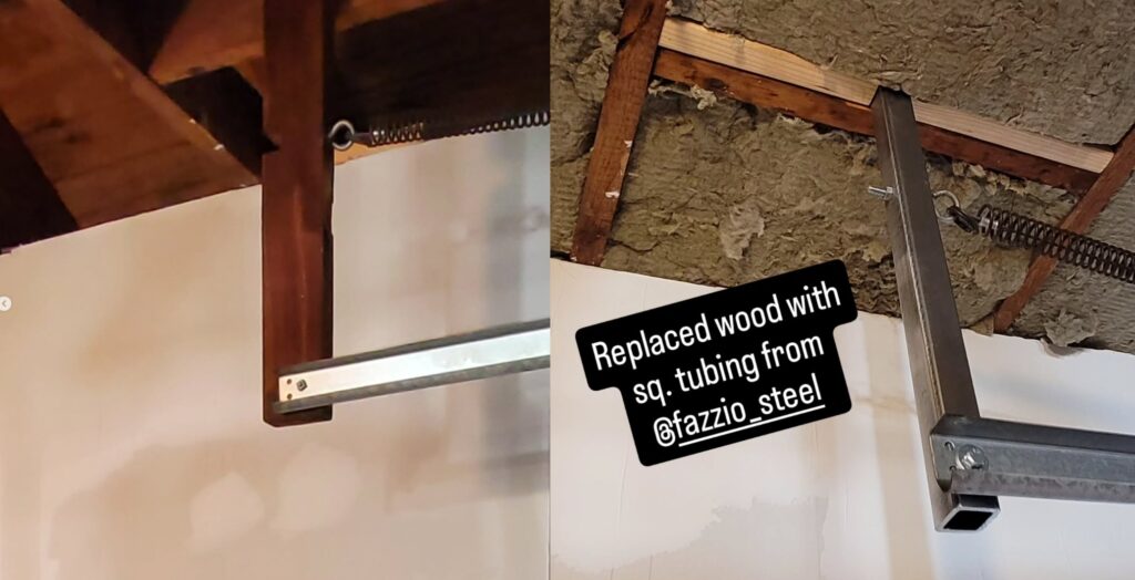
I’m becoming more comfortable working with metal as you can see here. I replaced the wooden garage door track support with steel tubing. I used my drill press to make these holes.
March 2025
This is an important month where all things that I have been working on up until this point have collapsed into building my DIY Plasma CNC.
What are the Chances: Uncle’s Lathe
I bought another Atlas lathe but this one works. Browsing Facebook Marketplace I saw it listed by my cousin. My uncle was a machinist at Mobil Refinery, which is where I worked. And I felt this is a sign. My cousin already had other offers but he accepted mine because he wanted to keep it in the family.

Flux cored welded supports onto the lathe table legs.
Casters are now welded to the lathe table legs.
The lathe is now positioned on the table. It is very heavy.
Beginning DIY Plasma CNC Fabrication
Ready to begin cutting the pieces for my DIY Plasma CNC table.
But first, I need a fixed feed roller for my miter saw station. This is a Woodworkers Warehouse Miter Saw Station Feed Roller. Woodworkers Warehouse was amazing but short lived. I’m repurposing the roller for this miter saw station. And I grinded the edges down to expose clean metal for easy welding.
Tack welded the roller to the cart. Pre-Metal-Fabrication-Me would have drilled holes and used nuts and bolts. That would have been boring. Sparks are so much better.
The feed roller can now be positioned into place using the screw lock. It’s been very helpful in the fabrication of my projects.
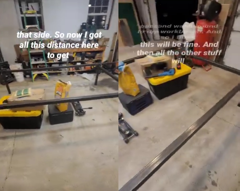
Making first cut for the Plasma CNC table. This will consume my time through September 2025.
March 23, 2025
This is my very first cut for the Plasma CNC made on March 23, 2025.
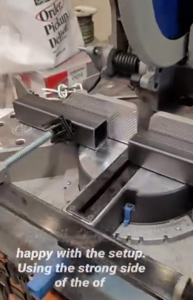
Miter Saw Tip: I found that this saw has a strong side and a weak side. The left fence is weak and can’t be used as a reference point. The right fence is ridged and doesn’t flex as much when the workpiece is clamped in place.
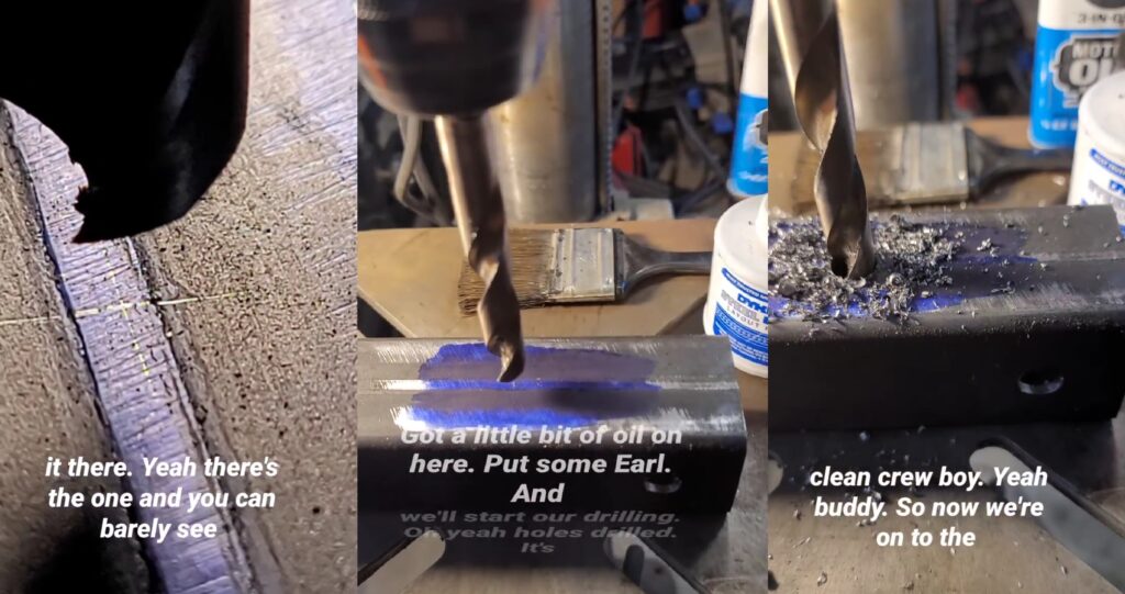
Using my drill press to make the first holes on Plasma CNC frame. I learned a lot during this time. I had to redo this piece as I developed a more accurate method. Drilling through the seam is very difficult. Using my phone to zoom in on the workpiece was excellent. We really take this piece of technology for granted as we use it to help us do many things, including being a microscope for fine machining.
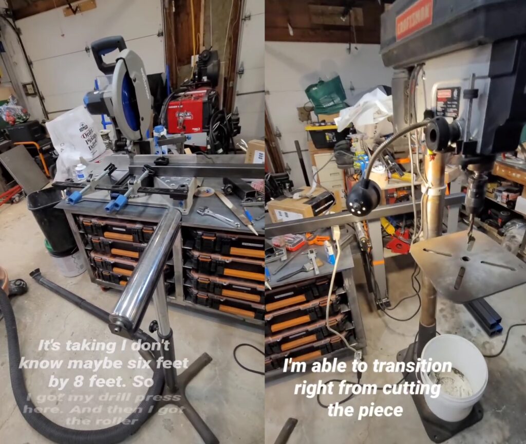
Miter Saw Station and Drill Press Workflow
Utilizing my space wisely I setup my drill press in front of my miter saw station. Once a piece is cut I can transition it to the drill press where I can drill the holes.
Repeatable Center Drilling for 2-Inch Tubing
Using this quick vise that came with my drill press I was able to dial it in to get perfectly centered holes across the 2-inch face of this tubing. Since I’m using the feed roller I had to dial that in as well with my calipers. I did this by measuring the distance between the drill press table and the bottom of the tubing as it spans the clamp. The hole must drill through at the exact same point on the other side (as close as it can be all things considered). If my feed roller was up too high or down too low then the hole would be shifted on the opposite side. Thanks for your help, Pythagoras.
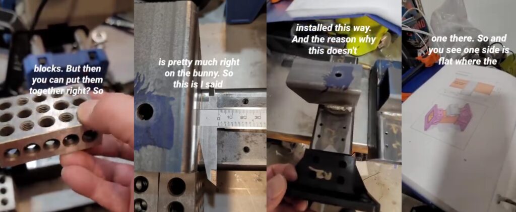
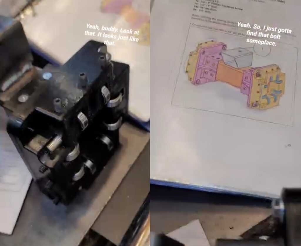
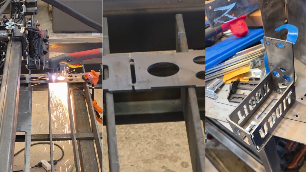
Preparing Plasma CNC Bearing Blocks
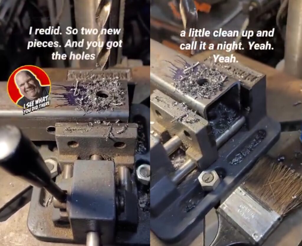
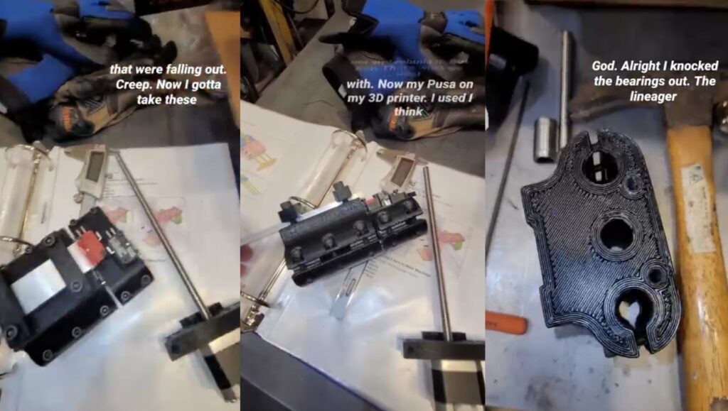
The bearing blocks are assembled with 3D Printing Bearing Blocks that are attached to a 2 1/2-inch piece of square tubing using 10-32 pan head screws. Having these end caps aligned perpendicular to the tubing will be helpful during fine tuning of the gantry slides. I’m not rushing through this.
I used a transfer punch to make a center punch within the center of the hole. This didn’t work so well for me. Although the indent was made in the center I was not successful in getting the drill bit perfectly in the center of the indent. Looking back I would have rather drilled and tapped it while the 3D Printed bearing block end-cap was in place.
![]()
Plasma CNC Gantry Supports
Welded the X-Axis Gantry Supports to the Y-Axis Gantry Tubes using MIG Welding on my Lincoln Electric 210 MP.
Using 123 Blocks to establish a reference to the face of the tubing so that the start of the Gantry Support will sit flush with the edge of the tubing. The hole on the top of the support is how the X-Axis Gantry Tube will be mounted to the Gantry Supports. It serves as a pivot point for the X-Axis if the Y-Axis is not trammed.
Assembly of Bearing Blocks
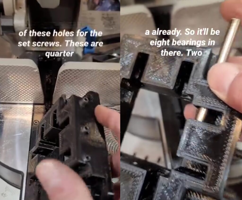
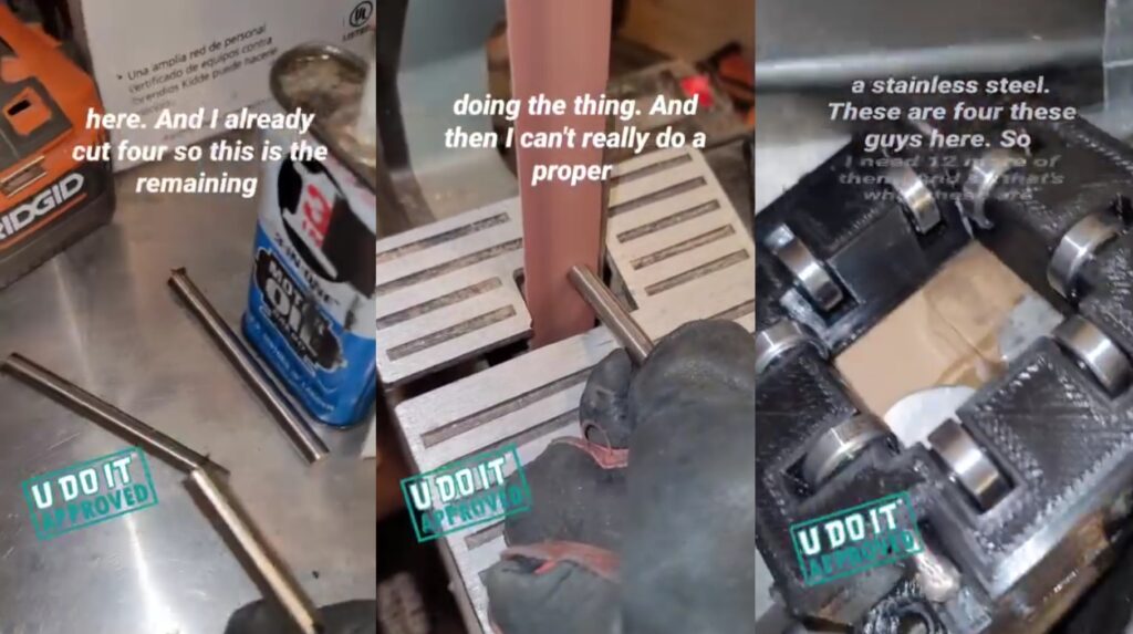
Cut 8mm stainless steel rod to 3 1/4 inches in length and these get pushed into the bearing blocks while lining up the bearing and bearing washers in the holes.
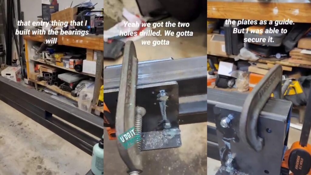
Drilling Y-Axis Tubes
I learned that I could use the smallest center punch to line up with my mark. These tubes are 10 feet long and I need to choose a reference point from only one end on each when I drill. Although the tubes are 10 feet long they are not exact so all measurements must be taken from a single reference point.
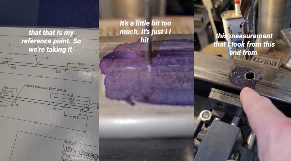
Using Tape Measure Instead of Layout Fluid
Another pivot in my measurement style is using my tape measure to position the workpiece under the bit. The bit here is the smallest center punch and the contrast of that over the yellow tape measure makes this task easier. This quick clamp vise is positioned perfected so that the drill will go through the center of the tube (front to back). And, the drill bit will also go through the exact same position on the other side of the tube because the tube is perpendicular to the drill bit..
No Room for this Plasma CNC in my Workshop
Notice the footprint of the Plasma CNC frame. After assembly it will occupy a 10 feet long by 6 feet wide area. This is not the place for it. I switched to Fusion 360 to create a floor layout plan in my workshop. The floorplan takes into account the doors and windows.
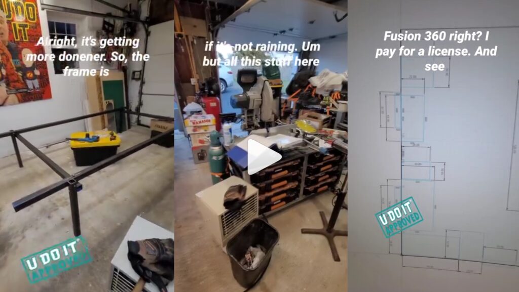
Workshop Floor Plan
I’m satisfied with this floor plan as I’m using it today (January 2026).

April 2025
April is the month where things come together rapidly.
Implementing Floor Plan
Rearranged the workshop based on the plans.
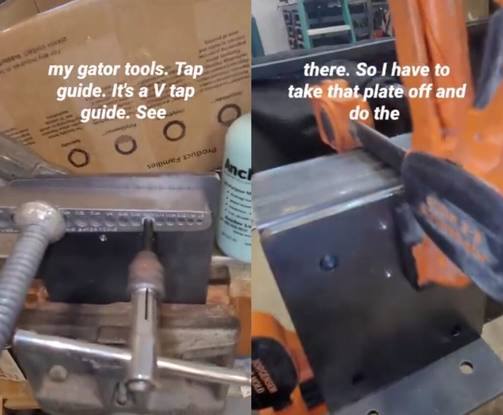
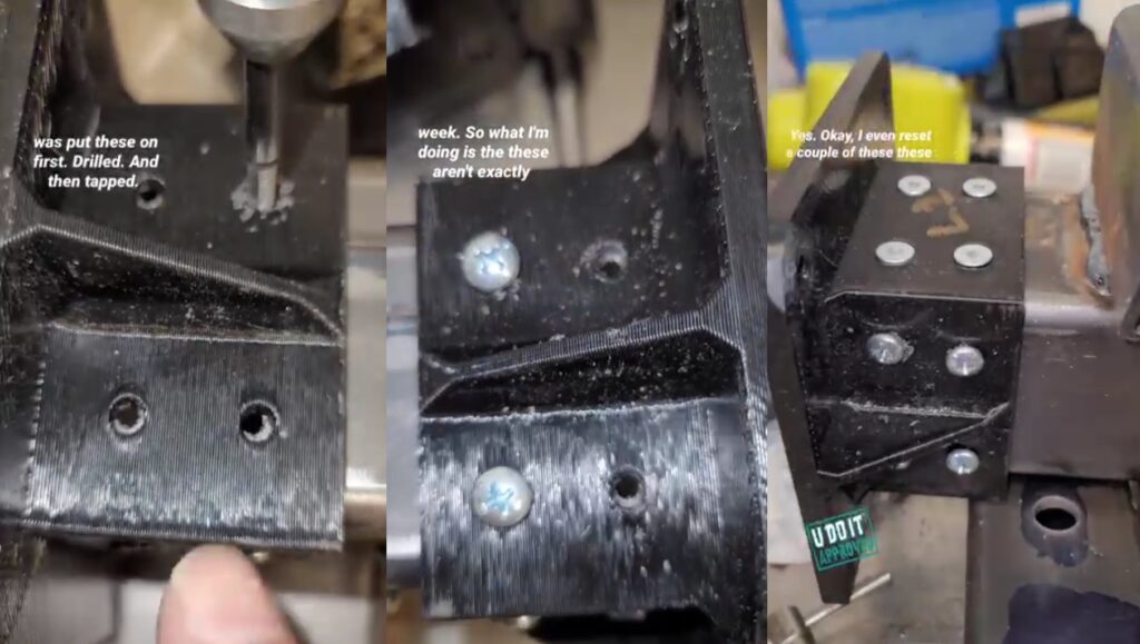
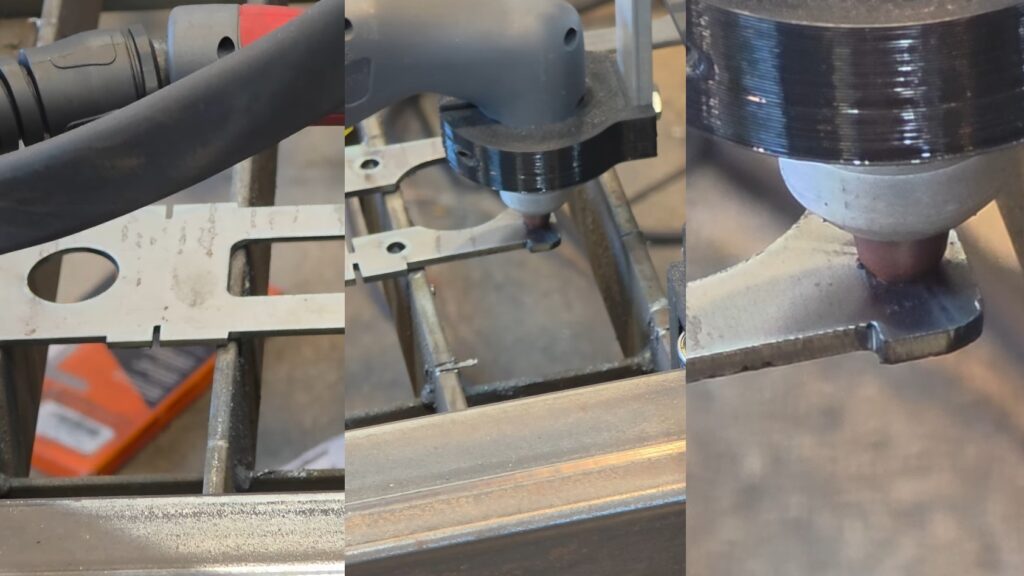
Tapping Mounting Plates
I ordered the precut plates from JD’s Garage. They cut the 1/4 inch plates using the same Plasma CNC that I’m building. The holes are used for the belt mount and tensioners and need to be tapped with a 10-32 tap.
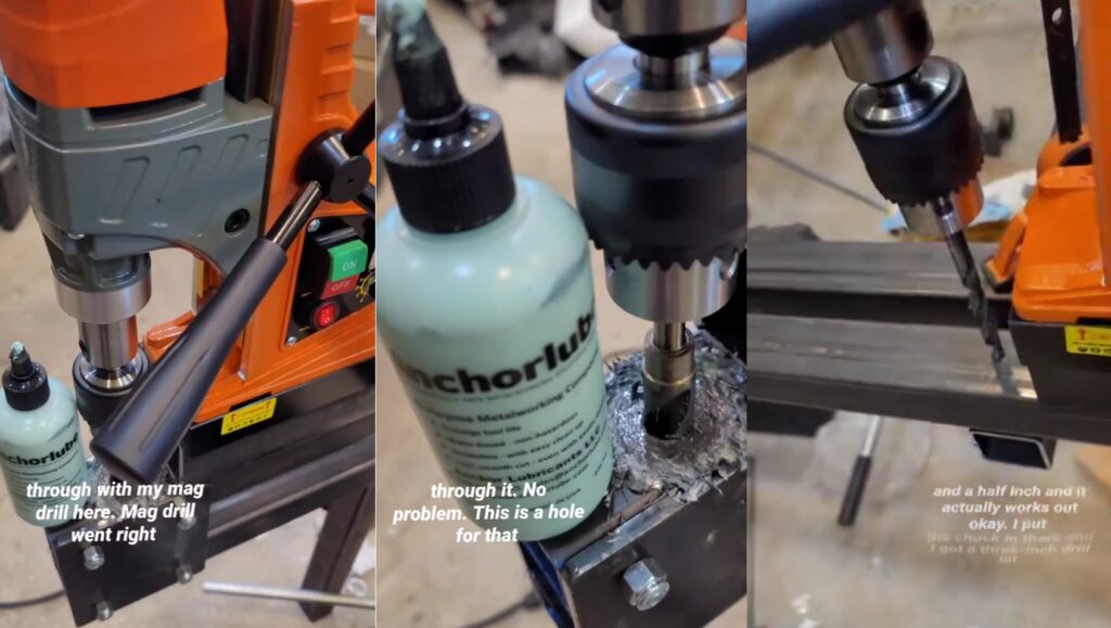
I recently discovered Anchorlube thanks to a friend on instagram. He’s been mentoring me through this process as he builds huge BBQ units that need to be towed by a truck. This stuff is magic. And, it’s tips like these that I’ve been acting upon as soon as I receive them.
To ensure proper tap alignment I’m using my Big Gator Tools V-Drill/Tap Guide secured with a C-Clamp.
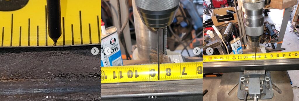
Drilling through Tubing
To ensure parallel alignment of the upper and lower Y-Axis tubes I sandwiched another 2-inch tube in between them. Using the same referenced ends I positioned the tubes over one another and verified vertical alignment. Anchorlube made this work go quickly but it requires a lot of force against the workpiece for the drill to work properly.
Deburring Stainless Steel Rods
The woodworking tools are definitely helping during this build. This is the delta 30 inch belt sander removing the burrs from rod cut with a carborundum cutting disc. These rods are inserted into the four holes in the bearing blocks to secure the bearings and bearing washers. There is a newer version of this bearing block that has the washers part of this model. But, I was lucky enough to have the first revision.
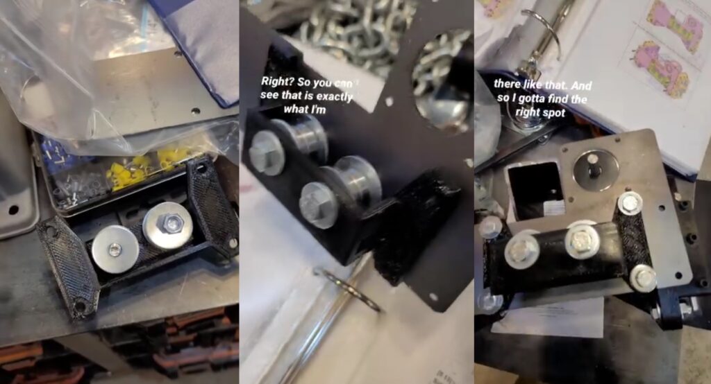
Building and Adjusting Bearing Blocks
The rods are pushed through with a bearing sandwiched in between two 3D Printed washers. The set screws are used to adjust the position of the bearings against the Y-Axis tube.
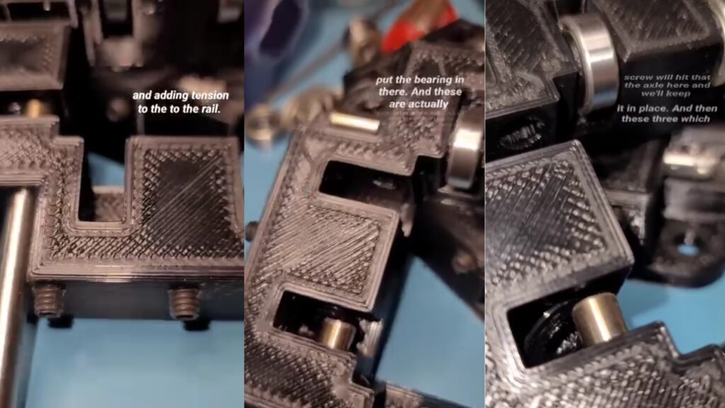
The end caps are now secured on the Gantry Tubes with pan head screws and counter-sunk screws. You can see the alignment issue I have with the holes on the 3D Printed part and the drilled holes in the metal. The next time I have to do this I will drill directly through the 3D Printed part’s holes into the metal. Although it will create heat, it will result in a more accurate hole placement.
Time to install onto the Gantry Tube.
Mounting Belt Channel and Stepper Motor
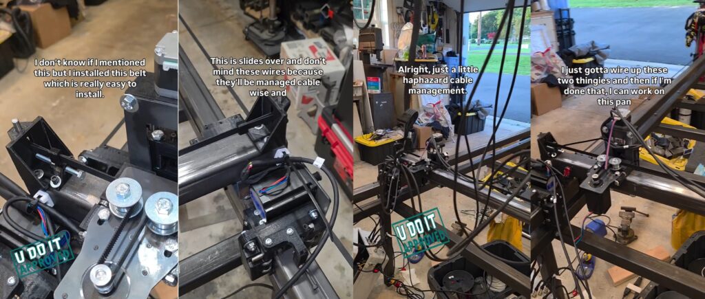
I’m impressed with this build. Although I’d rather have a rack and pinion gear for rigidity, this GT2 belt system allows for rapid assembly. I’m thinking about how to retrofit this to switch out the belts for a rack and pinion.
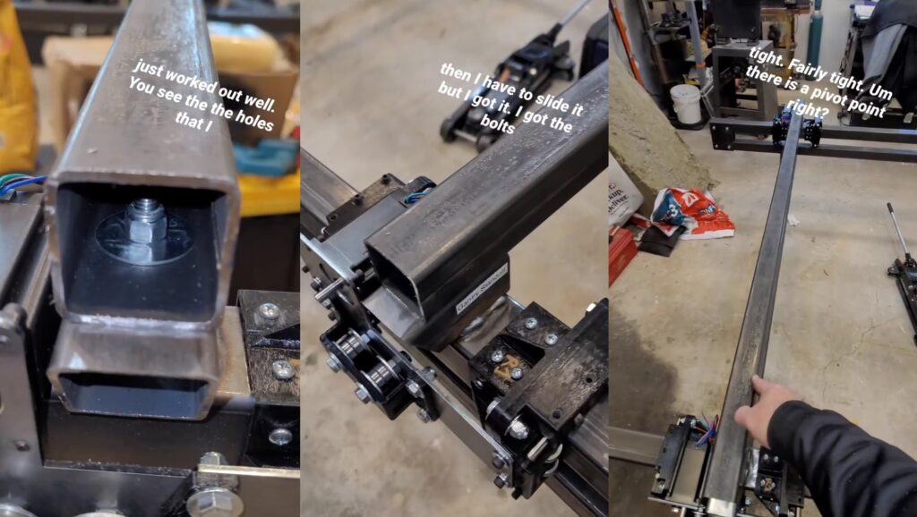
Assembly of X-Axis Gantry Tube
Once the Gantry Mounts were installed on the Y-Axis Tubes it was necessary to level them by adjusting the tilt. Installation of the X-Axis Gantry Tube is made with bolts, fender washers, and nylon lock nuts. These serve as a pivot point for alignment correction once the X-Axis is trammed with the Y-Axis.
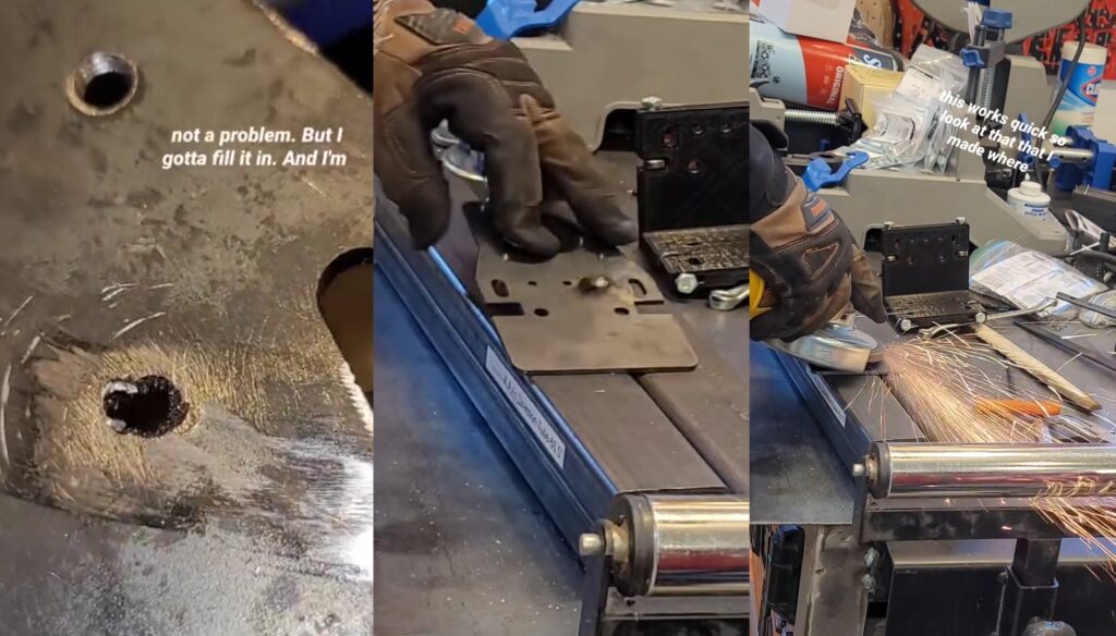
Assembly of X-Axis with Problems
The X-Axis plate has three holes that require tapping but the tap broke in one of the holes. I’ve never encountered this but I can tell you that drilling out a tap is very difficult. With this new hole I need to fill this and drill/tap again.
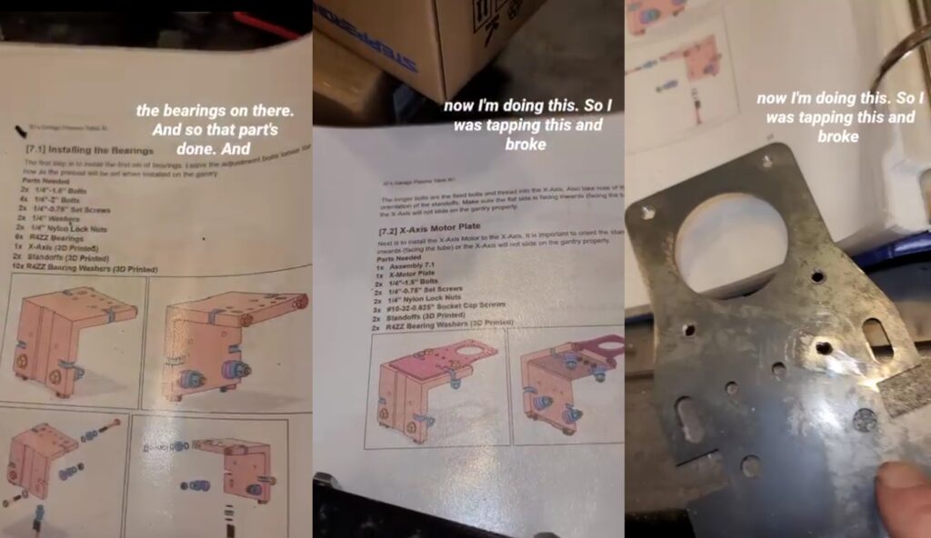
This mistake was a great learning experience because I was able to fill it in with my welder, grind it down, drill it, and tap it.
I leveled up with a new skill and completed assembly of the X-Axis Motor Plate.
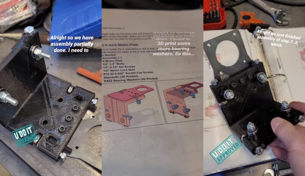
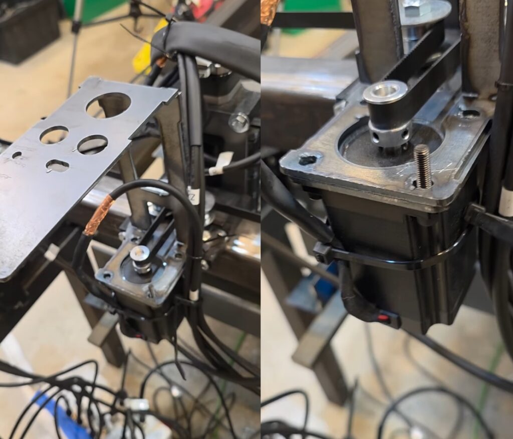
Mounting of Stepper Motor on X-Axis Motor Mount
Mounted the X-Axis Stepper Motor onto the motor mount. The set screws adjust the force that the bearing applies to the X-Axis Gantry Tube. For several cuts with the finished plasma CNC I never adjusted these and there was a lot of play. Once I adjusted them it operated better.
Facebook Marketplace Find: My Uncle’s Lathe
I think this one was a sign. I bought an Atlas lathe but it was missing some parts and would be expensive to fix it. And ever since then I’ve been scanning the marketplace for one in better condition. I found one and was like this looks like it’s in great shape. And I looked at the seller and it was my cousin. I messaged him and he held it for me. It even came with a cart that my uncle made for it.
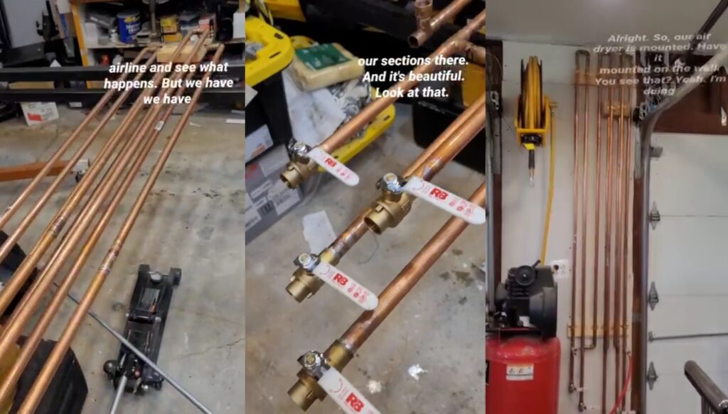
DIY Copper Pipe Water Separator for Plasma Cutter
I learned later that Plasma Cutting requires moisture free compressed air. As a compressor compresses the air it brings the moisture in with it. This moisture needs to be removed. Although there are several methods for water separation, I chose to construct my own DIY water separator using several sections of 3/4-inch copper pipe, ball valves, elbows, and couplings.
May 2025
May 2025 is where the appearance of progress accelerated since the Plasma CNC Frame was built and the air dryer was fabricated.
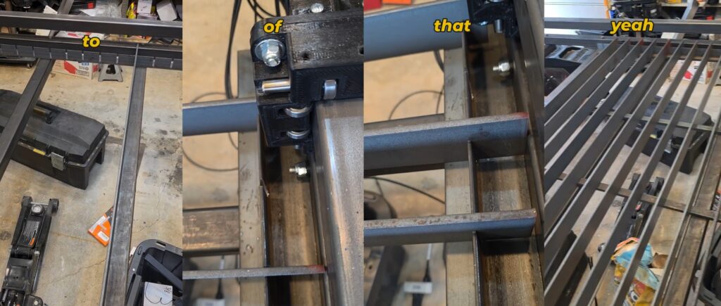
Adding Crossmembers to Plasma CNC Frame
Using a mag-drill to drill into the 2-inch square tubing with the help of Anchorlube.
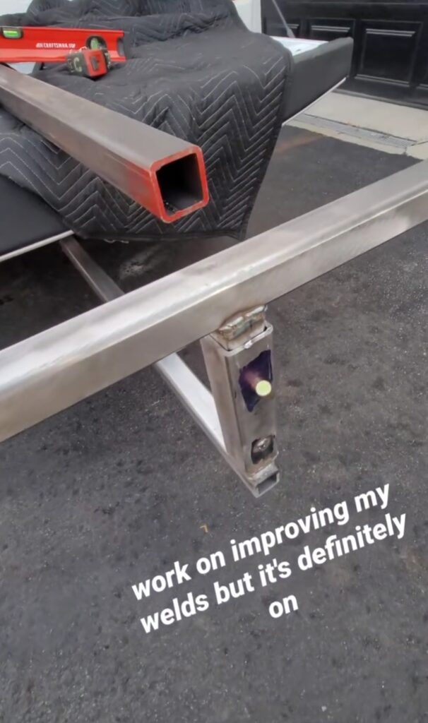
Side Quest to Fabricate Trailer Ramps
Assembly of Z-Axis
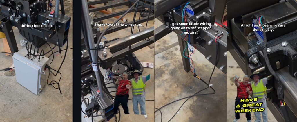
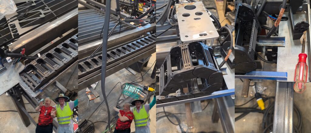
Plasma CNC Electronics
While this is built according to the plans and schematics I have been doing research and found a creator who provided important information regarding Plasma CNCs and Spindle CNCs. These devices emit a lot of EMF and can cause the controller to stop in the best case or crash in the worst case. One of the suggestions was to add ferrite beads across power and signal leads.
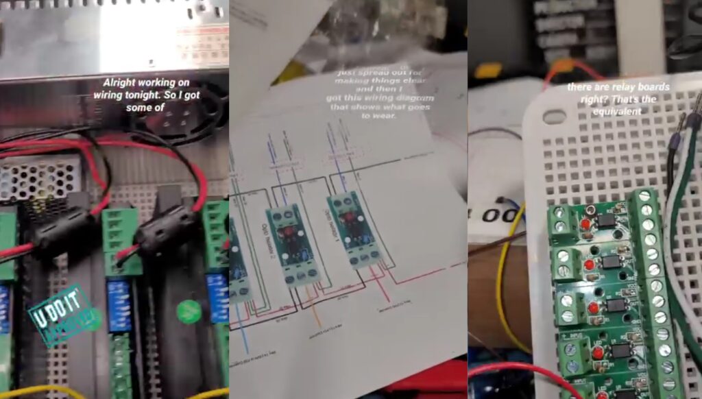
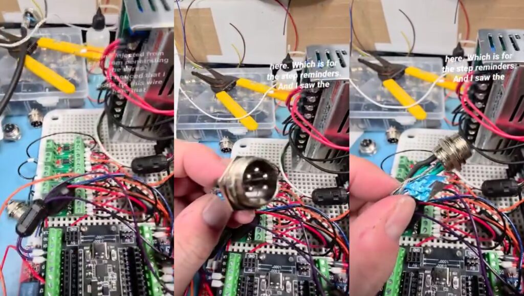
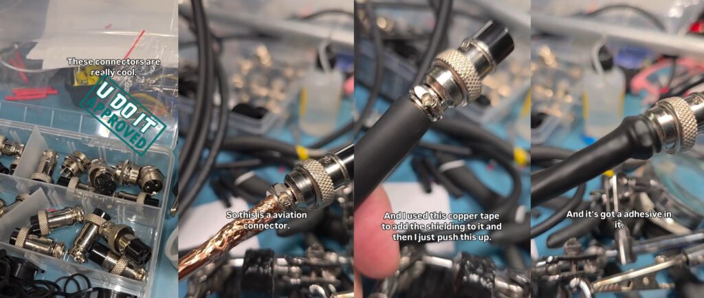
The double shielded wiring is soldered to the aviation connectors. For proper shielding I’m using copper foil tape to maintain the shield from the braided wire up to and including the connector. The enclosure is plastic, so what’s the point. I decided to wrap the entire enclosure in this foil tape.
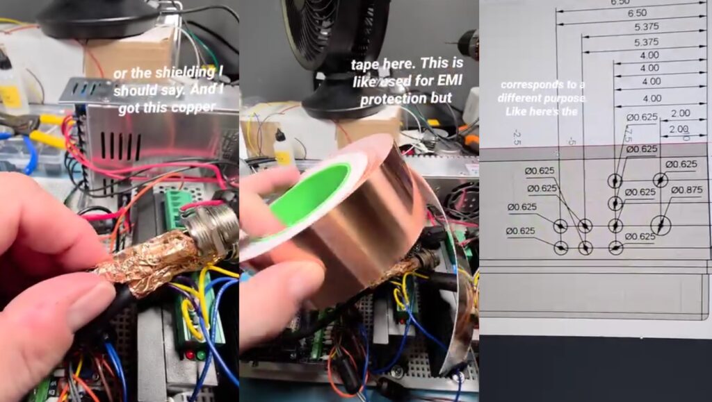
I created a drill template in Fusion 360 based on measurements in the plans. And 3D Printed it on my Prusa Mk2s. Then taped it to the enclosure and drilled out the holes for the aviation connectors.
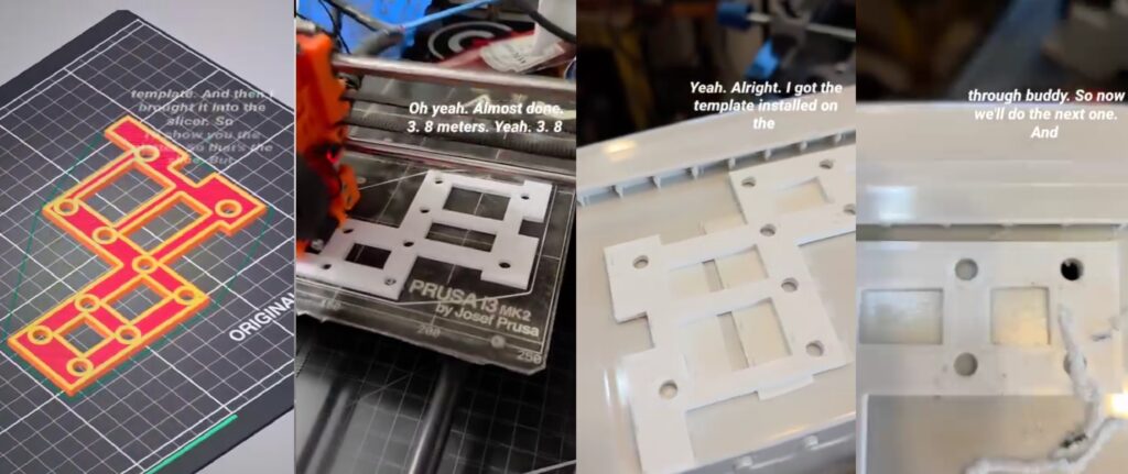
Holes drilled and labeled. Aviation connectors installed and shielded. Enclosure interior shielded with copper foil tape.
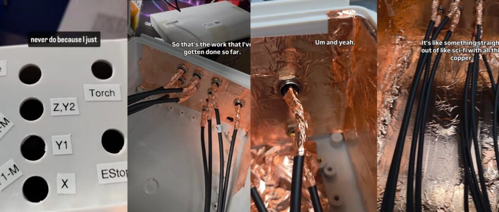
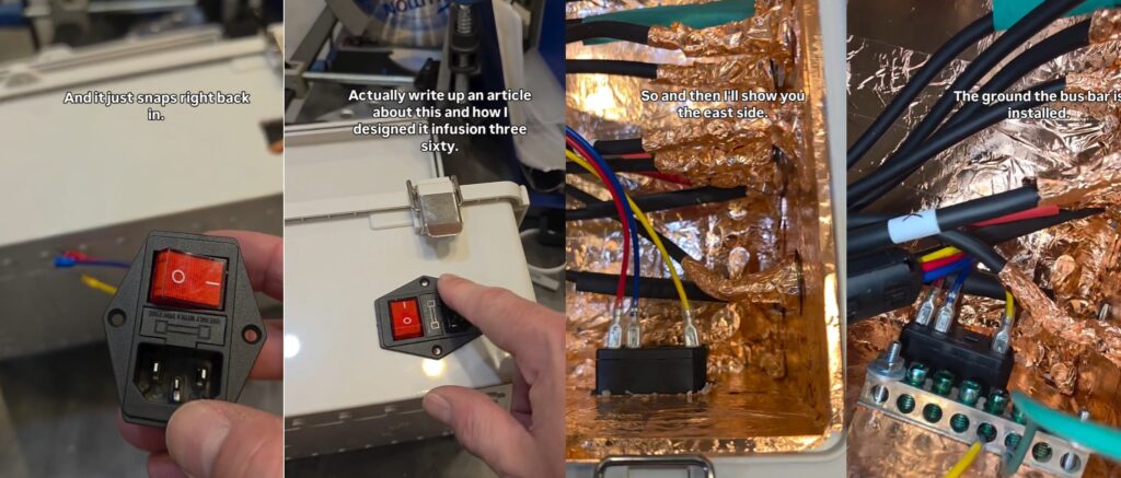
Using an IEC C14 fused plug and switch combination for the AC power to the Plasma CNC Controller. Also installed an AC ground bus bar for all AC grounds to be tied together along with the interior shielding.
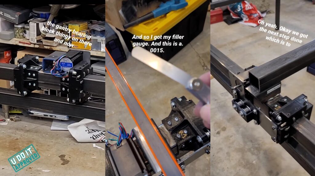
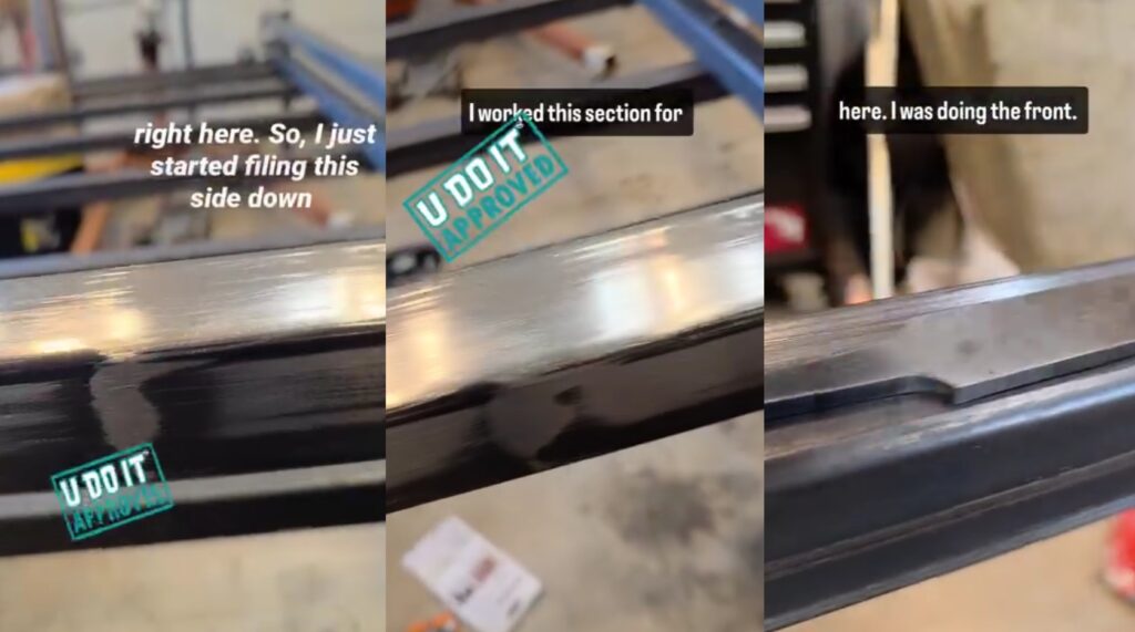
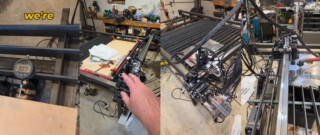
Checking Z-Axis and X-Axis Movement
While moving the Z/X-Axis I noticed a stiff point along the run. You could see a section of the tubing where it was not flat. Using my metal file I filed the tube down with several long strokes. This is an incredibly boring but necessary process. Then I validated it with my dial indicator.
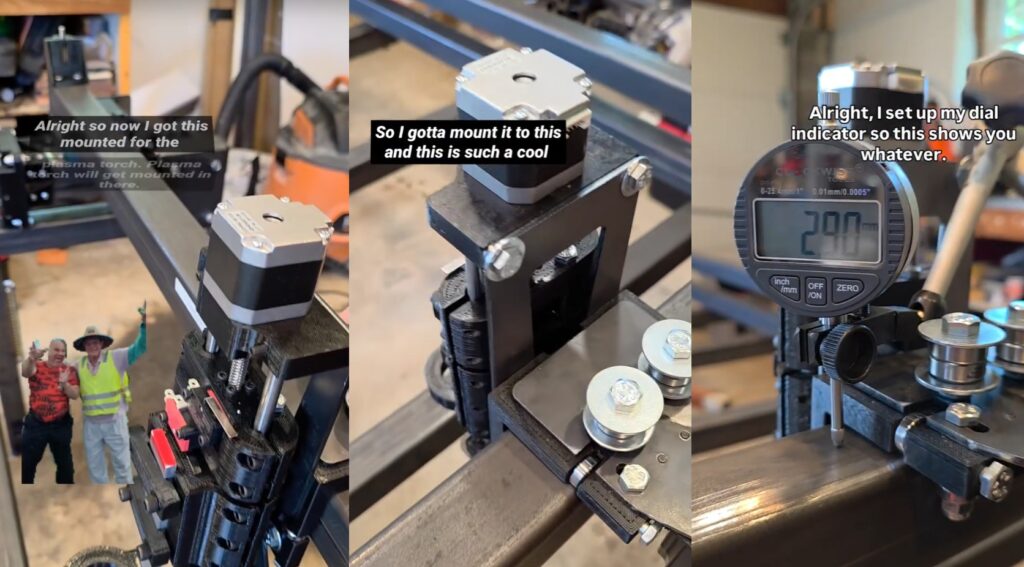
Filing down X-Axis until it glides along without a high spot on the areas where the bearings roll over.
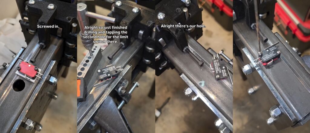
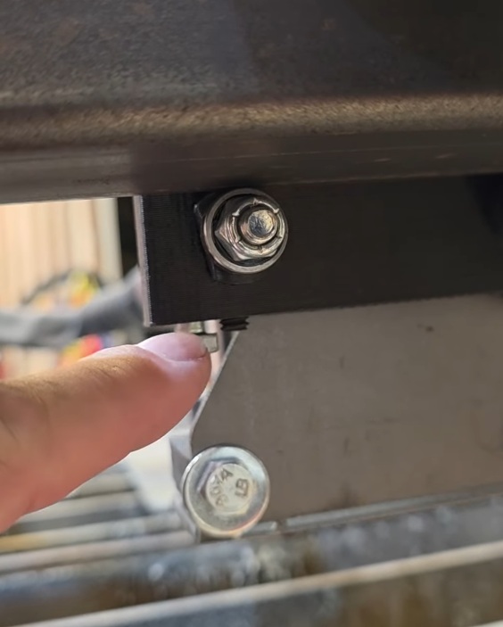
Drilling and tapping holes for limit switch installation. These socket cap screws protruding out from the bearing blocks are adjustable to help tram the X-Axis across the Y-Axis.
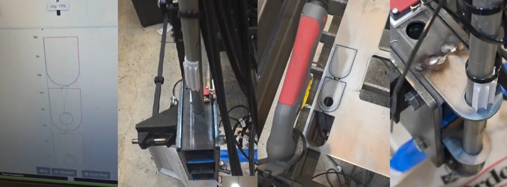
Making Cables for Motors and Limit Switches
Using the 4 wire or 2 wire double shielded cable to make the Plasma CNC wiring. Wrapping the interior with copper foil tape and then wrapping the outer connector with heat shrink tubing that has adhesive inside it.
June 2025
This is the month where significant progress is made.
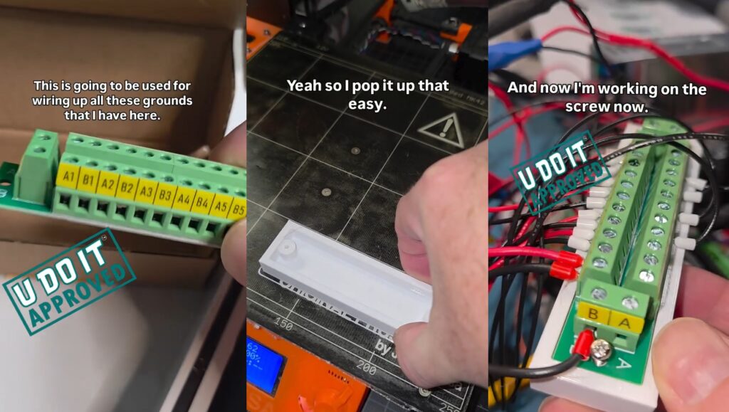
5V Power Distribution
I purchased a terminal block to replace the daisy chained power connections to each device within the controller. This version didn’t come with a mount so I designed and 3D Printed one. Each wire is connected with a ferrule and a little solder used to secure it within the ferrule.
Wiring Stepper Motors
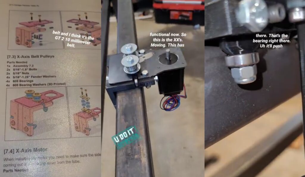
Y-Axis Belt Installation
Installing Y1-Axis and Y2-Axis belts. Also 3D Printed zip tie mounts that I screwed into the X-Axis Gantry Tube to secure the Y-Axis stepper motor and limit switch wiring.
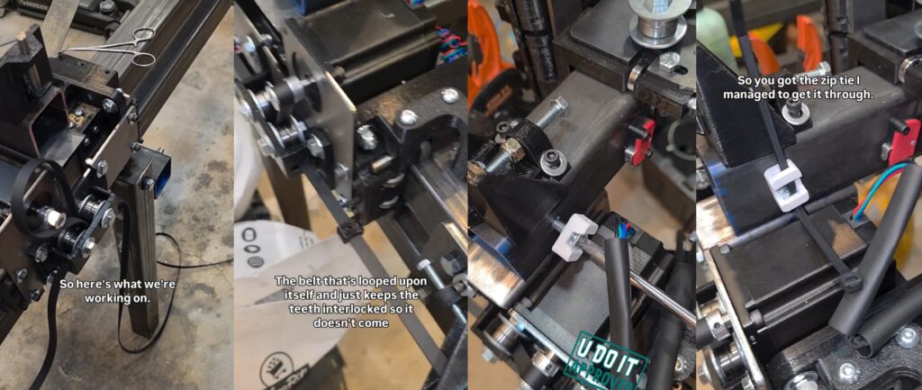
X-Axis Belt Installation
Plasma CNC Table Slat Installation
The material to be plasma cut will reset on slats. The slats are 1/4-inch thick and stand 2 inches tall. They reset in the slots cut in the upright side of angle iron.
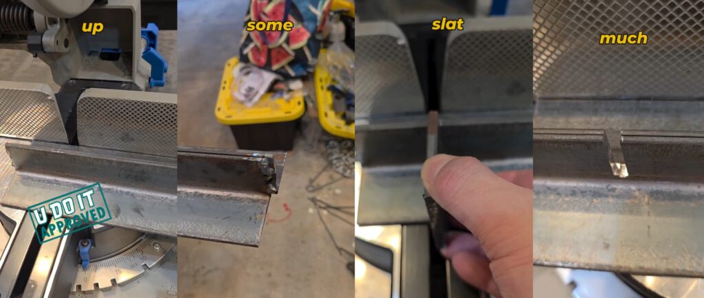
The slats sit in the slots cut in the angle iron and rest on four parallel pieces of 3/4 inch thick flat bar for a consistently flat surface. Notice that the slats are too long in the 2nd and 3rd photo. I need to cut each one down so there will be room for the Gantry Bearing Blocks to roll passed each slat.
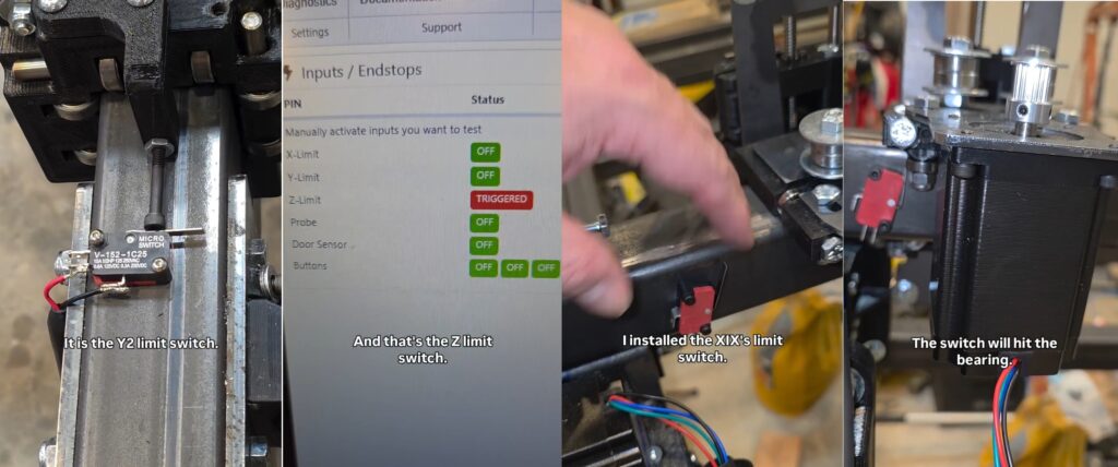
Debugging Limit Switches
There are limit switches for the X-Axis, Y1-Axis, Y2-Axis, and Z-Axis. And there is also a Probe Switch for the Z-Axis. Below I’m debugging the Y1 and Y2 limit switches but it is showing the Z-Axis limit switch is triggering. And I’m demonstrating the X-Axis limit switch trigger point.
September 2025
My birthday month is September and it was a banger month. So much was completed in this period of time.
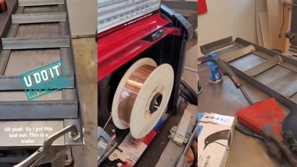
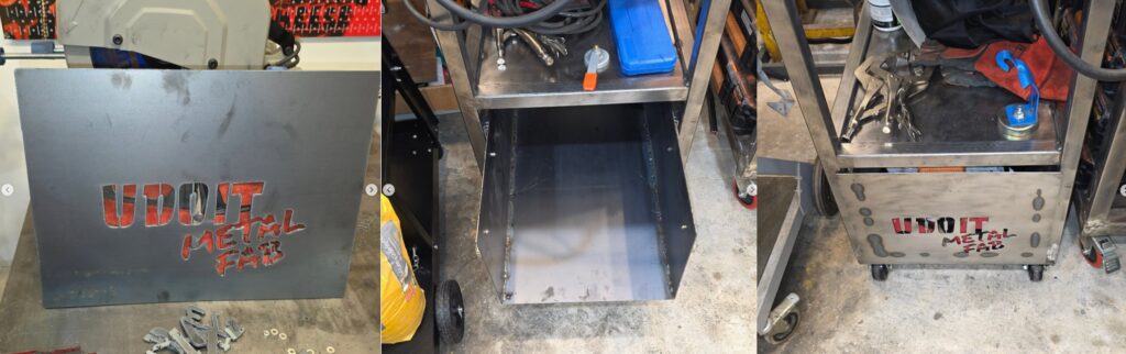
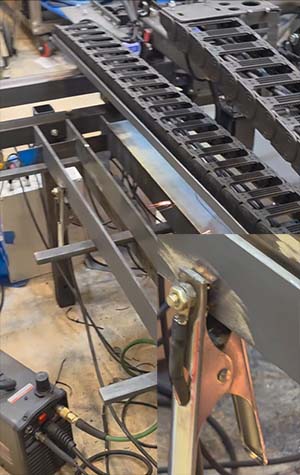
Welding Cart Build
I purchased a VIVOHOME welding cart but it wasn’t big enough for my Lincoln Electric 210MP welder and 7-inch cylinder. I decided to build one, which is the right of passage for a beginning welder. To prepare for this I cut the pieces to the desired lengths and removed the mill scale with my Eastwood SCT.
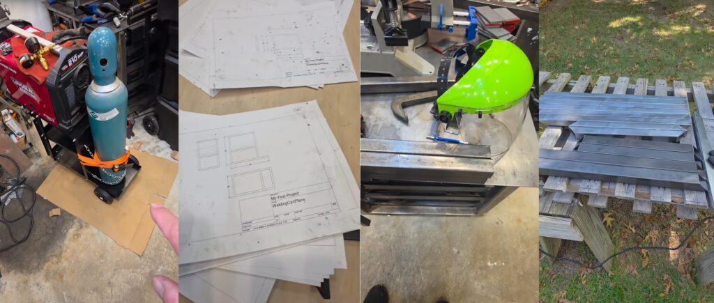
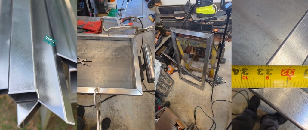
Welding Cart Frame is complete and need cross members and shelf welded in place. To avoid error I used my number punch set to mark each piece accordingly. And can’t weld until the mill scale is removed.
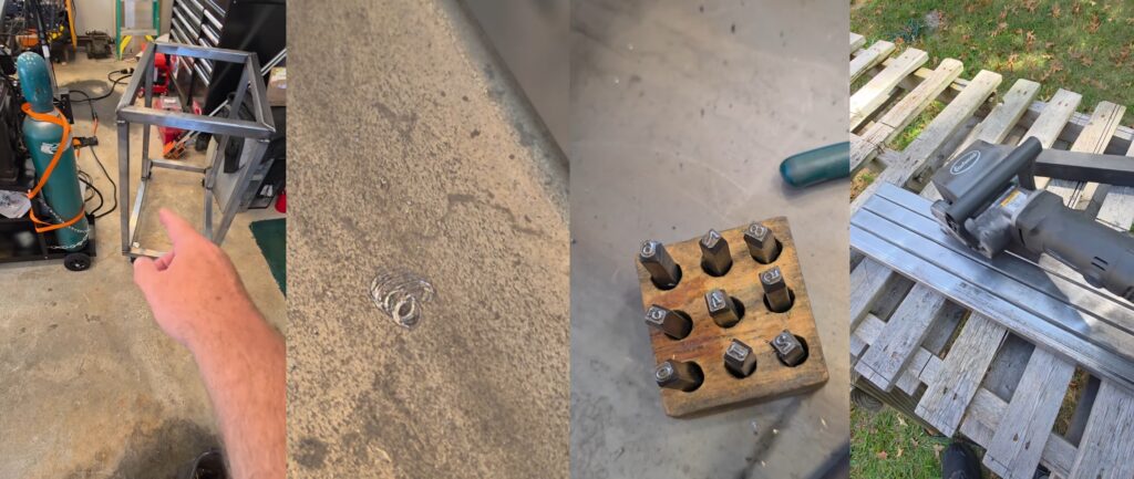
Numbering each tube helped me keep my sanity while laying out the crossmembers. Everything fit snug and may have required a little convincing.
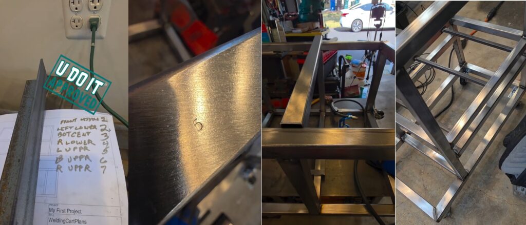
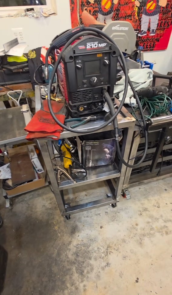
Cut the sheet metal for the top and middle shelf. Moved everything from the VIVOHOME welding cart to my newly crafted welding cart.

Welding cart is finished. Up next is the drawer that requires a working Plasma CNC.
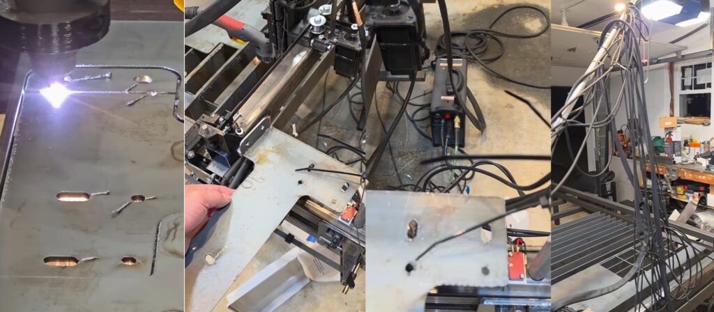
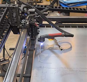
First Cut on Plasma CNC
Trammed the X-Axis Gantry relative to the Y1-Axis and Y2-Axis using my Clockwise Tools Dial Indicator along with a box level as a true surface. And practiced some dry runs cutting out a piece for my welding cart.
First cut on the plasma CNC did not completely pierce this 1/8 inch steel plate. With the help of online friends they suggested I slow down the feed rate from 80 inches/minute to 40 inches/minute. This worked well. This is that off-cut I’m using from the miter saw table top.
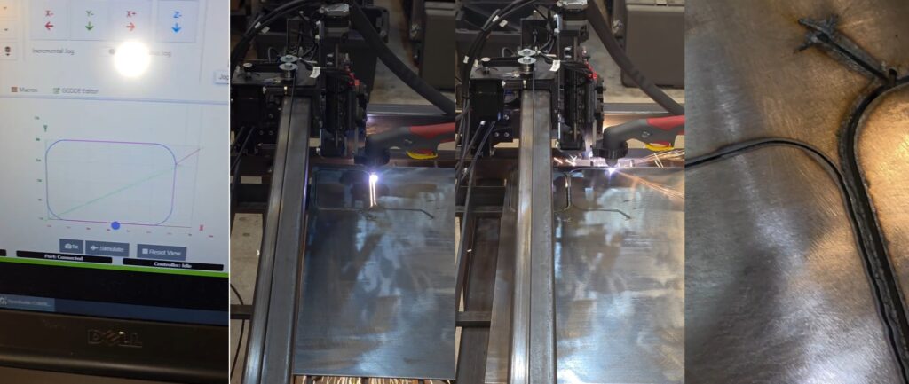
My first cut was not successful because it was 80 inches/minute for 1/8-inch steel plate. However, my second cut went straight through because I had the feed rate set to 40 inches/minute.
![]()
I mentioned the play in the X-Axis from not following the tightening instructions in combination with the uneven surface from the previous cut.
The other cuts were perfect as you can see here.
October 2025
The Plasma CNC is working. I’m dialing in my tooling in Fusion 360 and learning about the cutting parameters.
Cutting X-Axis Drag Chain Mount
This is based on JD’s Garage Drag Chain Mount but with U Do It cut in the side of it.
Missing Relief Cut
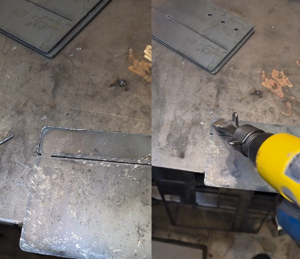
There should be a large relief cut between those two relief cuts in the middle of the support. But, I missed this in my Fusion 360 drawing and tooling. The relief cuts allow you to easily bend a piece accurately across a wide distance on a metal part without a metal brake. This relief cut can be filled in by welding the seam. However, I do not own a metal brake. A brake is a tool that gives you leverage to bend metal. This 1/8-inch steel would be tough to bend without a brake. Because it was missing I need to retool based on a known reference point. I’m using the center of the bottom left hole as this reference point within Fusion 360 to create the large relief cut. The torch nozzle is tapered and fits in the center of the hole perfectly.
The edge of the relief cut appears to line up well with the relief cut, which will be enough to bend it as shown on the right photo.
Fitting the X-Axis Drag Chain Mount to ensure it will work as expected. The socket cap screws used to mount the X-Axis Stepper Motor to the X-Axis Motor Plate must be replaced wit4h longer ones when this it attached.
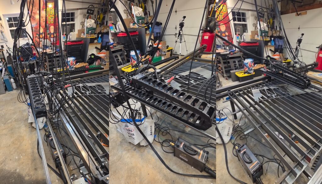
Drag Chain Mount
I designed a new part Drag Chain Mount that will support the X and Y chains. However, I discovered an issue where the mount will crash into the conduit that extends up to support the plasma torch cable bundle. To solve this, I decided to relocate the conduit to the end of the Y1-Axis Gantry Tube.
The slag on the plasma cut part is very brittle and can be snapped off with lateral force. This can be achieved with a screw driver, a wire wheel cup on an angle grinder, repeatedly dropping the part, placing it in a tumbler, or in this example using an air hammer. The use of the air hammer dings up the surface. But, I do not mind since this is a part for the Plasma CNC and not an art piece. It worked well but is a little loud.
In preparation for the drag chain mount I needed to relocate the Torch Extension Arm. The Torch Extension Arm, which is made from electrical metal conduit, is necessary to elevate and support the plasma torch cable bundle. In Fusion 360 I designed a tabs that could be welded to the Y1-Axis Gantry Tube. The bottom tab would be solid to hold the Torch Extension Arm in place.
Z/X-Axis Set Screw Adjustment
The Z/X-Axis tilts some. I discovered that it was because I didn’t secure the bearings onto the X-Axis. Using the set screws shown, I tightened them until the bearing force was enough to keep the Z/X-Axis from flexing while moving and cutting.
X-Axis Drag Chain Mount
I secured the drag chain mounts to the X-Axis Gantry Support Tubes using machine screws. This provides the required strength to support the drag chain, the wires within the drag chain, and the two pieces of 3/4-inch angle iron that spans the two mounts. The angle iron suspends the drag chain mounts to support the drag chain as it moves.
Welding Cart Drawer
I designed a drawer for my welding cart in Fusion 360 and cut it out on the plasma CNC. There were some mistakes that I had to correct after it was cut. And of course I didn’t discover this until I folded it up into the drawer you see below.
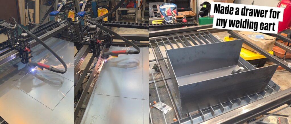
Mounted the drawer into the cart. Cut out the face of the drawer and welded it to the drawer.
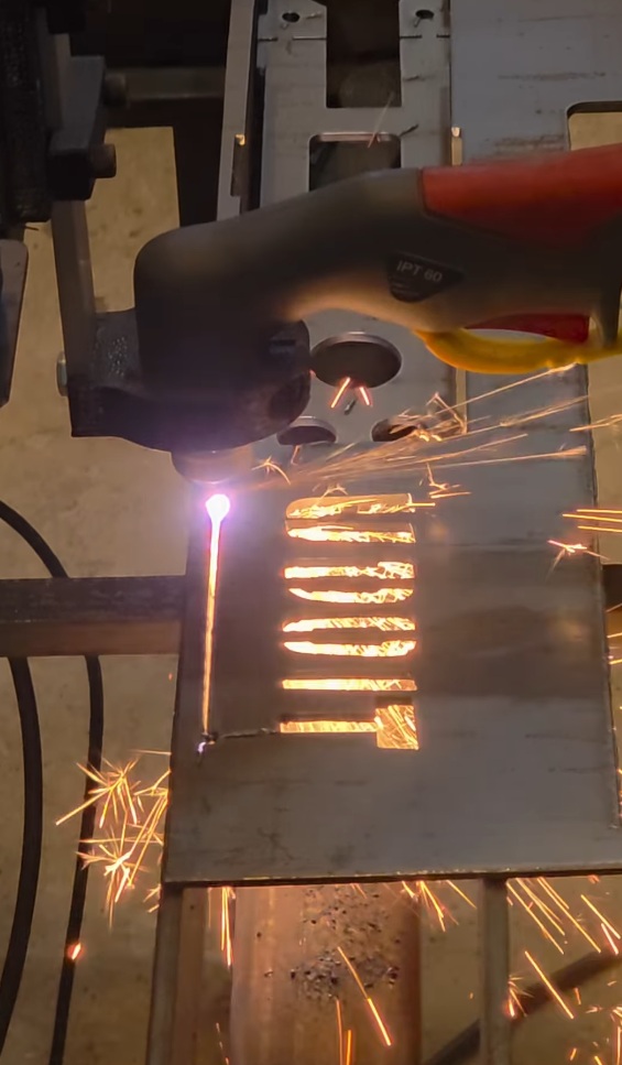
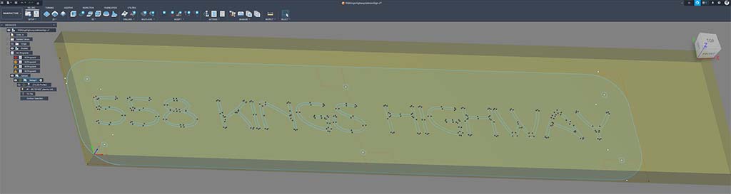
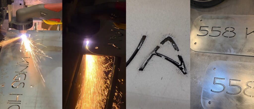
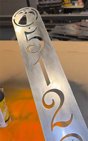
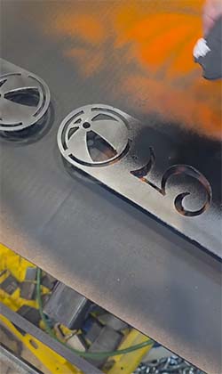
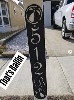
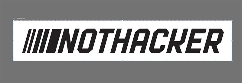
Address Placard
I wanted a script font of our address to be mounted on our mailbox post. I love how it turned out but there were some issues due to the tooling and the kerf of the plasma torch. Although I can’t use this one it was a lesson on how to spot these issues within Fusion 360 prior to performing the actual cut operation.
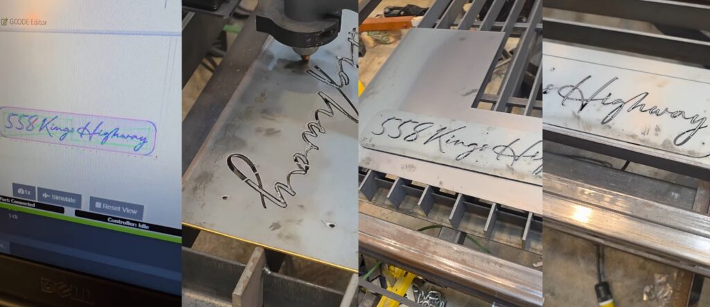
Now that I know what to look for within Fusion 360 Simulation I chose a different font that had more weight to it. I added bridging to the font within Adobe Illustrator. This modification preserves the internal shapes of a character. Plasma cutting removes the material inside of a cut. So bridging preserves look of the 8 and the A characters.

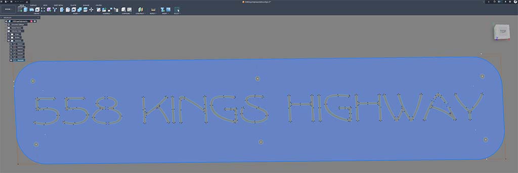
Fusion 360 Design
I have been using Fusion 360 since they first released it for makers to use. Fusion 360 has an intuitive interface and workflow for design and CNC machining. The design within Fusion 360 is known as Computer Aided Drawing. And the machining is known as Computer Aided Machining. Together, they are known as CAD/CAM.
The size of the placard is limited by the height of the lumber used for my mailbox post as well as the size of scrap steel I have leftover from prior cuts. This is about 4 3/4 inches high by 23 inches wide. I drew a rectangle close to this size and imported the above Adobe Illustrator SVG file into the sketch within Fusion 360. Using this rectangle as a boundary, I was able to position the address and size it appropriately. To please the eye with a little symmetry I placed six 1/4-inch holes around the placard and I rounded the sharp corners with filets.
Fusion 360 Machining
I selected Manufacture mode within Fusion 360 and chose the model that I created to create the code. Through a series of steps I was able to create the code to cut out the address on my Plasma CNC.
An Updated Address Placard
For me, this entire process has been quite the learning experience.
I love the look of Rustoleum Universal Flat Black as a finish.
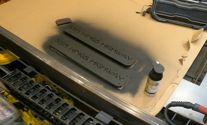
And it looks great against the white background.

Hanging Mailbox Sign
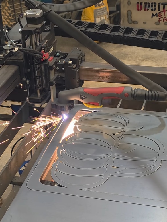
The moment I constructed my mailbox post I knew I wanted a spot for hanging a sign or a flag. So I left a large overhang about 30 inches wide. And now that my DIY Plasma CNC is functional I get to checkoff one of those dreams I had over 6 years ago. It’s fall and this season is perfect for a set of pumpkins cut out of steel.
I began with some basic artwork and cleaned up the vectors within Adobe Illustrator so that everything would work well with plasma cutting.

Then, I created an SVG file from Illustrator that I imported into Fusion 360. I wrapped the extents with a frame created from two concentric rectangles that would touch all four edges of the pumpkins. Added holes at the top for hanging from hooks.
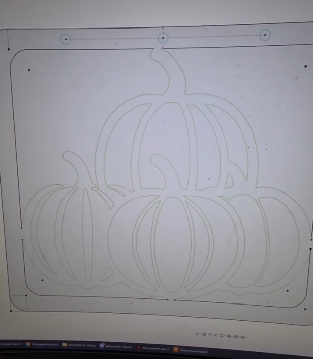
Cut the pumpkin design out of 14 gauge steel on the Plasma CNC.
And I protected the sign with Rustoleum Universal Flat Black and accented it with Rustoleum Orange. I tried not to make it perfect.
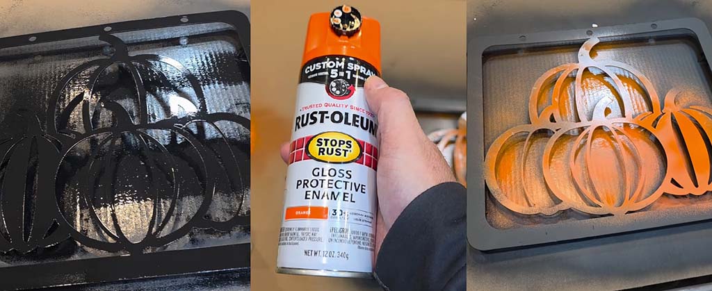
Then I hung the sign using two eye hooks and s-hooks.

December 2025
December was a great month for combining welding and plasma CNC creations. I encountered some issues and found ways to overcome them.
Another Address Placard
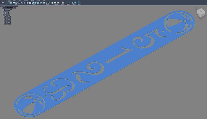
My efficiency with design to product is improving with each sign. So, I’m using Fusion 360 to design a vertical address placard with a beach ball theme.
Cut out of 14 gauge steel on the plasma CNC.
Then I removed mill scale using a wire wheel.
Painted with Rustoleum Universal Flat Black.
Hung the address placard using galvanized Simpson Strong-Tie Structural Screws.
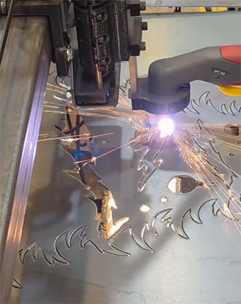
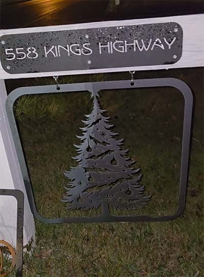
Christmas Tree Mailbox Sign
Using the same frame style with it’s holes for hanging from the post for the pumpkins I imported a Christmas Tree SVG file into Fusion 360. I modified the artwork some so it created a stronger plasma CNC friendly metal art piece.

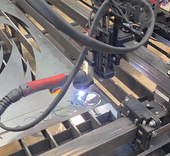
Every minute on the Plasma CNC provides opportunities for new lessons. In this cut I encountered flameout about 30 seconds into the cut. What I discovered was the ground clamp for the Plasma Cutter was not on a good spot. It has been working perfectly up to this point. At least that is what I thought. A Plasma Cutter requires a good ground connection to cut well. The plasma arc requires a good conduction path back to the Plasma Cutter. I used my grinder to remove mill scale from the steel and moved my clamp to this spot.
I reworked model to remove the large middle cutout from the tree. Then I ran this new job to continue cutting out the sign. The torch is following the line that was already cut but will continue on it’s path to cut the rest.
Here’s the change in the model where I removed the large cutout.
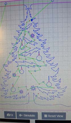
The cutout was complete but I didn’t remove it immediately since I needed to make use of the void space and cut out a different piece of art.
I did not apply a finish to it and just hung it up as bare metal. Eventually, it rusted with a brown patina.
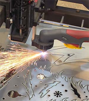
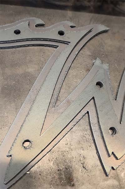
Wildwood W Cutout
Using the same sheet of steel that I finished cutting out the hanging Christmas Tree sign I wanted to make use of the unused steel. Maximizing yield is a goal of mine since this 4 ft square sheet of 11 gauge steel cost around $42. The Christmas Tree cutout is approximately 1/4 of the sheet. I created a new job from these two highlighted pieces that bolt together with flange nuts and socket cap screws.

Here’s the two pieces as seen within OpenBuilds CONTROL interface, which is the application I use to control my Plasma CNC.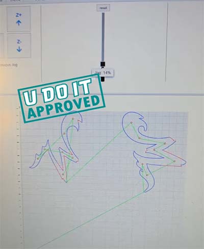
And I especially enjoy watching this level of nesting that can be created while maintaining the existing home position, which is the starting point for the job.
What’s cool is the design just worked. The pieces line up exactly with their registration holes for securing one to the other.
Next, I bolted the two pieces together and polished them for a nice metallic look.
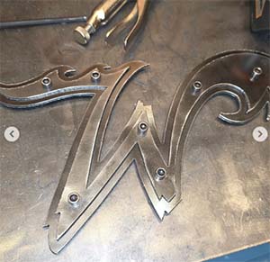
I gifted this to Harry Wild Ball, who is Wildwood’s Official Hype Ball!


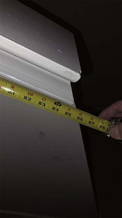
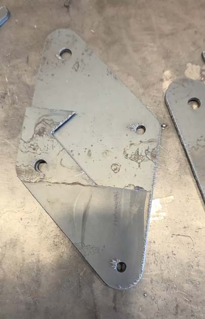
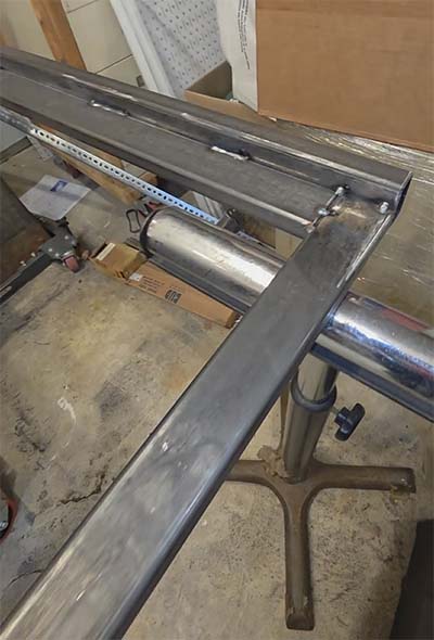
Stairwell Railing Fabrication
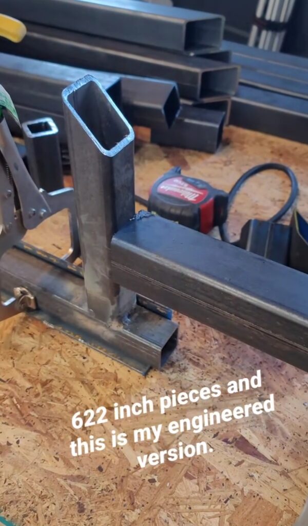
The stairs in our stairwell has an angle of 41 degrees and a length of 85 inches from the top wall to the bottom wall measured along that 41 degree angle. I want to fabricate a railing out of 1-inch x 2-inch that has a 1/8-inch wall thickness to give it strength and rigidity.
The drawing below, which I created in Fusion 360, shows two vertical lines representing the walls and the line at 41 degrees represents the plane that the railing would designed within. I drew a shape that represented what I thought would be a styling looking type of wall mount for the railing. The larger plate on the bottom left of the drawing is the top left plate zoomed in for reference. These plates will be cut on the Plasma CNC using 1/8-inch thick steel plate. The two large holes are for 5/16-inch lag screws, which are incredibly strong when screwed into a 2×4 wooden stud.
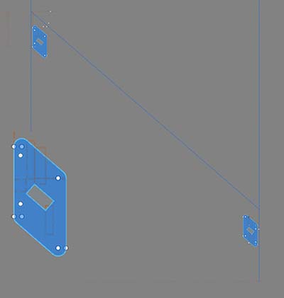
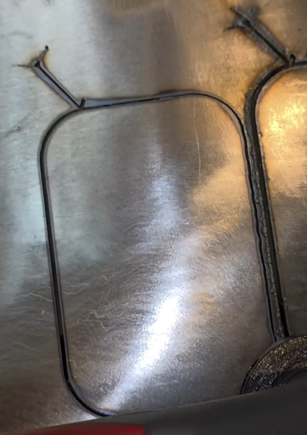
The two plates to the left were crafted out of a portion of each of the plates to the right. These will act as a template for accurately positioning the railing on the plate to tack weld it into place.
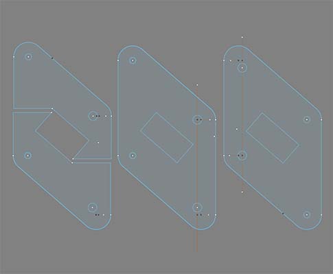
The plates and templates were cutout on the Plasma CNC.
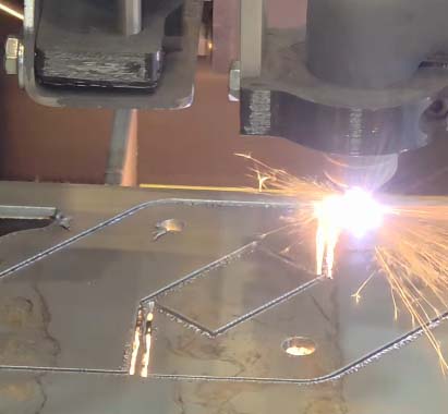
This is video of the plasma CNC cutting out the plates and templates. I’m making use of leftover steel from prior jobs to minimize waste.

The template will be clamped onto the plate to ensure the railing is tacked into place at the correct spot and angle.
Removed mill scale from the 1-inch x 2-nch steel tubing using my angle grinder and an abrasive disc.
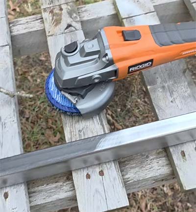
Cleaning Mill Scale
This cleans the mill scale off quickly but it consumed the entire disc as well as my battery..

Assembly and Welding of Railing
Tacked the railing on with the template in place. This ensures that the railing is properly aligned with the plate.
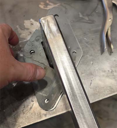
This shows how the template is used.

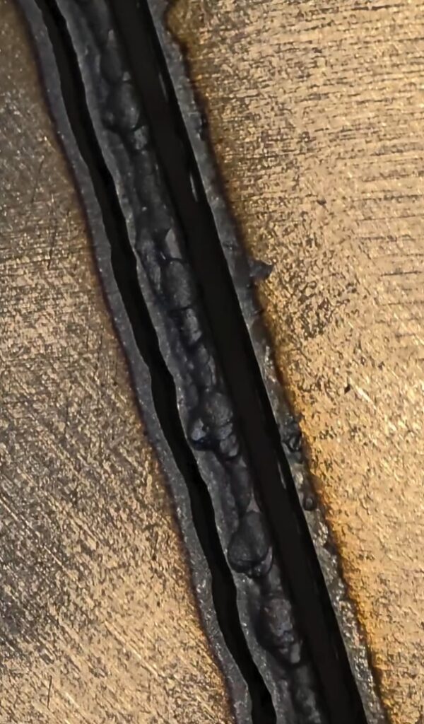
Railing is tacked into place. I learned later that tacking at the corners is better because of the humps that result when welding the root pass across the edge and the tacks. On the corners, the humps will appear but they are easer to knock down with grinding.
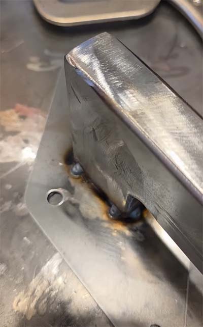
Welded using my Lincoln Electric 210 MP in the MIG welding process mode and cleaned up the railing using my angle grinder and a flap disc.


All of this is coming full circle by using my miter saw station that doubles as a welding table and a small parts organization solution. And, I’m able to easily access my small parts organizers and quickly locate the 5/16-inch x 2-inch long lag screws.

Painted and Hung
Hung the finished railing by wire across my cherry picker and gave it several coats of Rustoleum White 2X paint.

Who knew that 5/16-inch lag screws were actually 29/64-inch in diameter? I sure didn’t. So I had to break out the hole stretcher. The pistachio looking stuff is Anchorlube, which makes drilling and tapping so much easier.

When I measured the ideal placement of the railing plates I took into account the location of the studs within the wall. I’m using a clamp to secure the plate to the wall so I can verify its placement. Next, I drilled a pilot hole for the 5/16-inch lag screws.

Using 2-inch lag screws would provide a little less than 1 1/2-inch of bite within the studs. This is because the plate itself is 1/8-inch thick and the drywall is 1/2-inch.

And now this custom metal fabrication is complete. It is not only functionally strong and rigid but looks great.

Christmas Gift
I wanted to make a Christmas gift for our parents. I loaded up Adobe Illustrator and setup the graphic.
Then onto Fusion 360 where I drew out the idea and maximized the size to the width of a 4-foot sheet of steel. 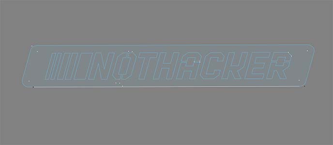
Setup the sheet and cut the sign out.

I Welded two pieces of rebar to the back so it can be staked into the ground. Then I gave it a coat of Rustoleum Universal 2X white paint.

Successfully delivered in time for our Christmas Eve family get together!

January 2026
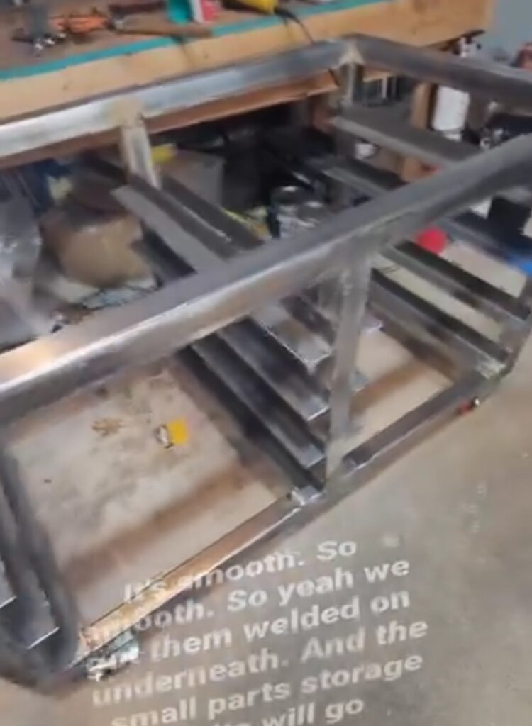
This winter is the time for organization and optimization of the workshop so I can efficiently work in the space. I have several things to fabricate, which include a panel storage cart for storing the sheets of metal under the plasma CNC.
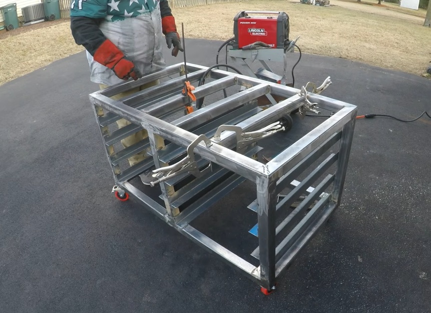
Panel Storage Cart
I have been purchasing sheets of steel but they take a lot of room in the garage. It is especially problematic when they are leaning against drawers or in front of storage cabinets that I require access. The cart needs to be 4-foot square with edges that will retain the sheets. And it will have two fixed casters and two rotating casters welded to the bottom. Then, another cart will be fabricated at a later date that will nest on top of this cart and can roll independently.
Cut all the pieces according to my drawings and welded them together.
Grinded down the high spots and welded on the casters.

Positioned the cart into place under the Plasma CNC.

Loaded it with sheets of steel and pushed it under Plasma CNC.
